

Fuel injection valve for internal combustion engines
a technology for internal combustion engines and fuel injection valves, which is applied in the direction of fuel injection apparatus, spraying apparatus, charge feed systems, etc., can solve the problems of fuel not being able to flow fast enough and the attendant wear of the valve body, so as to improve the fuel flow from the pressure chamber into the annular groove
- Summary
- Abstract
- Description
- Claims
- Application Information
AI Technical Summary
Benefits of technology
Problems solved by technology
Method used
Image

Examples
Embodiment Construction
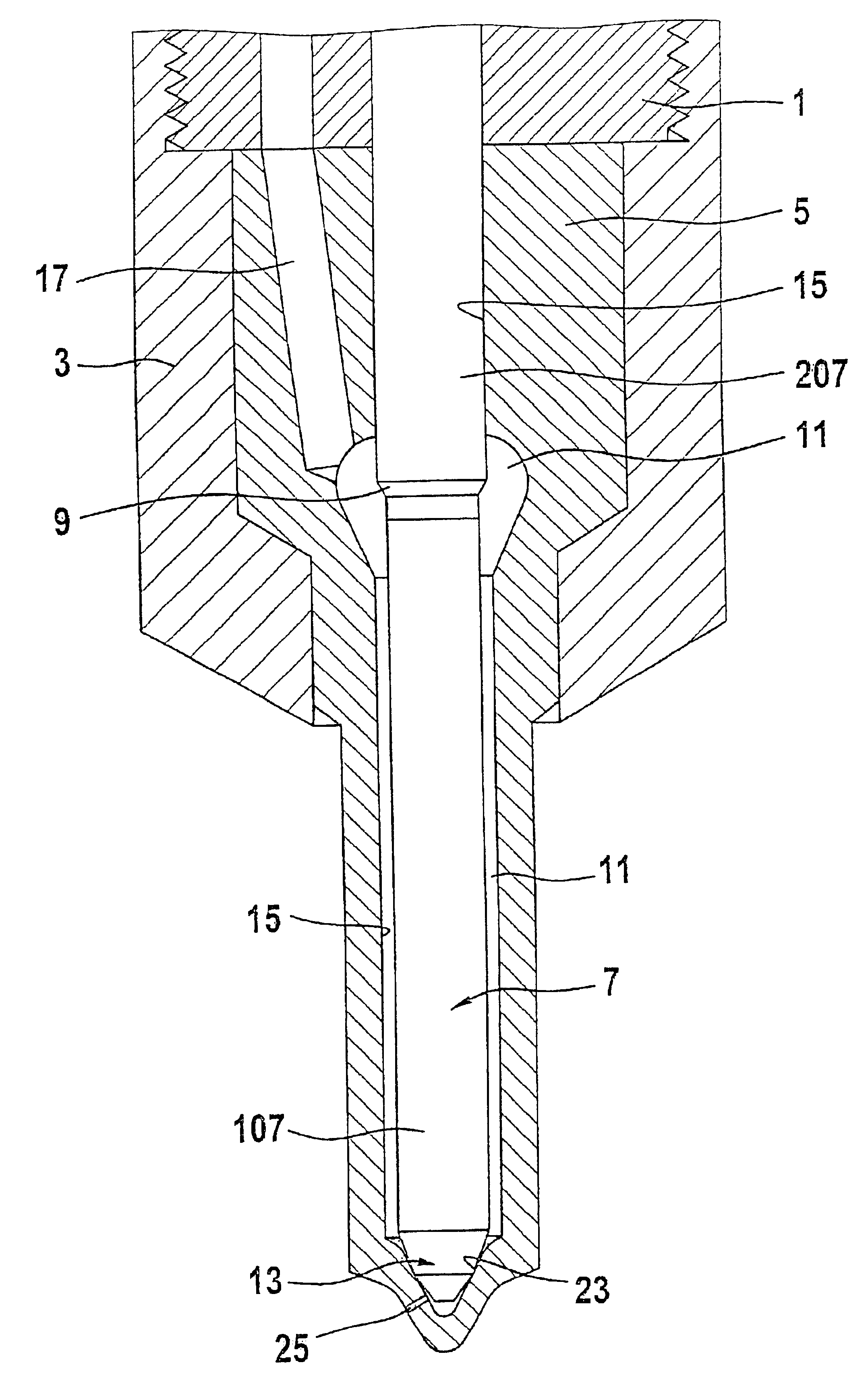
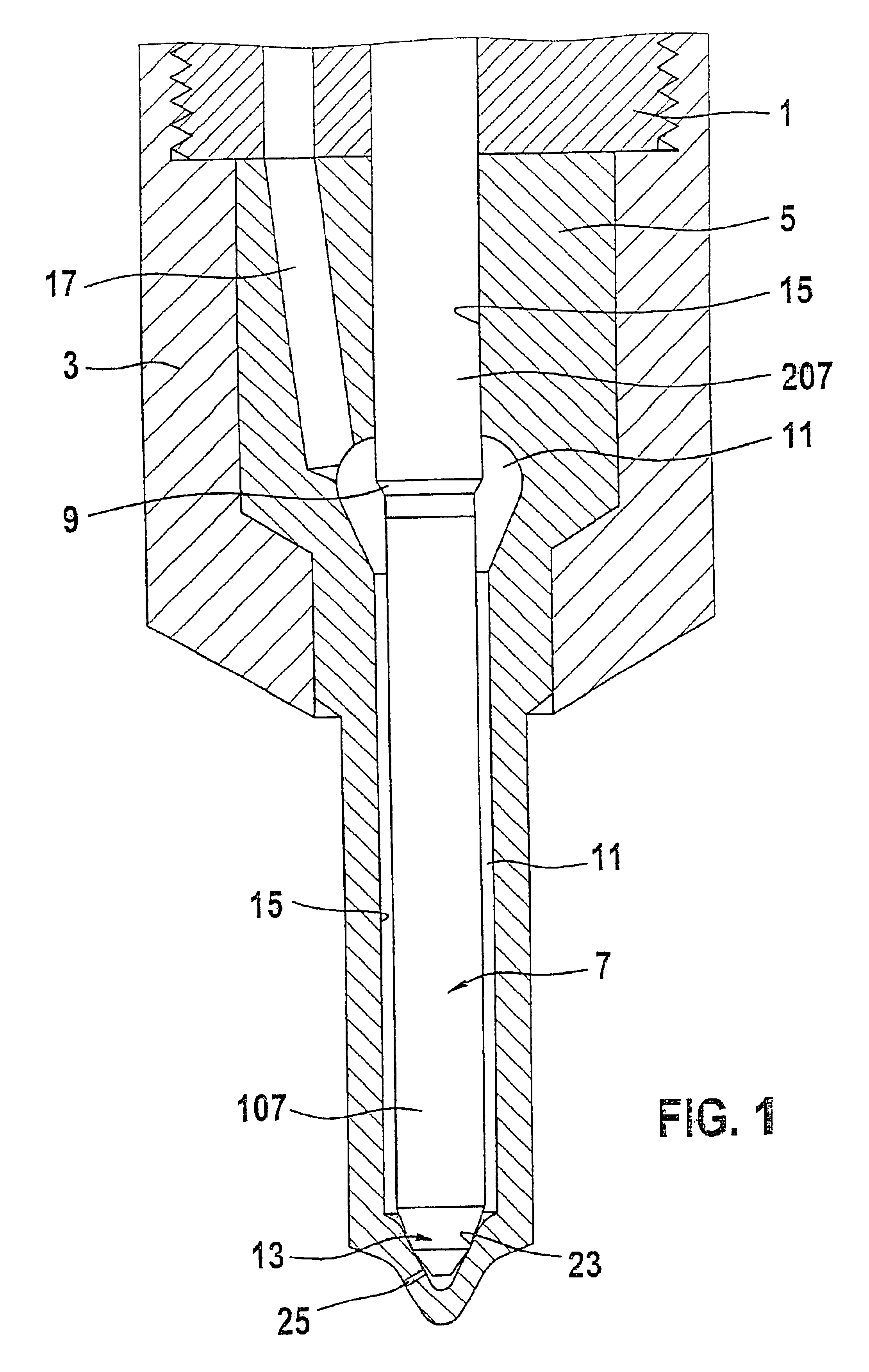
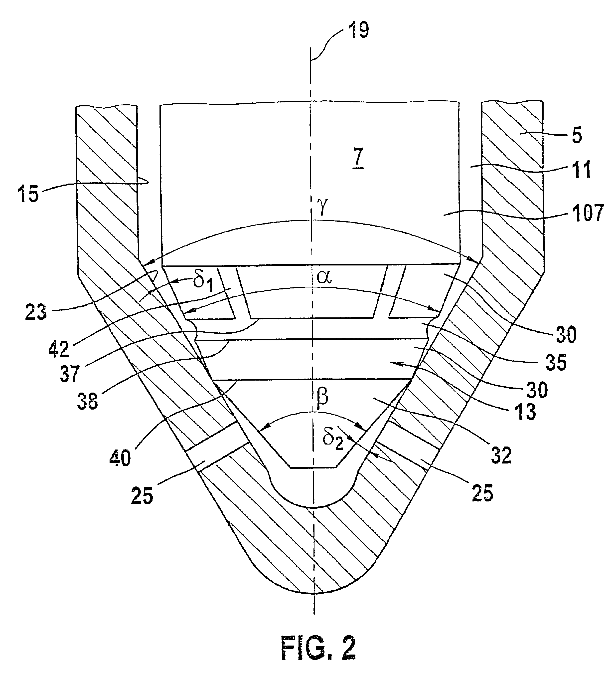
One fuel injection valve of the type with which this invention is concerned, is known from German Patent Disclosure DE 19634933A1. In this known valve, on the end toward the combustion chamber of the valve member,there is a valve member tip with two conical faces. A first conical face is adjacent to the valve member shaft and has an opening angel that is less than that of the conical valve seat. The first conical face is adjoined toward the combustion chamber by a second conical face, whose opening angel is greater than that of the valve seat, so that at the transition of the two conical faces, a sealing edge is formed which, in the closing position of the valve member,comes to rest on the valve seat, as a result of a closing force acting on the valve member.
The opening stroke motion of the valve member is exerted by the hydraulic force of the fuel in the pressure chamber, which in the closing position acts, among other effects, on the first conical face and thus causes a resultant ...
PUM
 Abstract
Description
Claims
Application Information