Fat heat exchange pipe with communicated inner fins

A heat exchange tube and flat tube technology, applied in the field of heat exchange tubes, can solve problems such as uneven internal pressure, and achieve the effects of improving service life, sufficient heat exchange, and improving heat exchange efficiency

Active Publication Date: 2016-05-25
SHANDONG UNIV
View PDF3 Cites 1 Cited by
  • Summary
  • Abstract
  • Description
  • Claims
  • Application Information

AI Technical Summary

Problems solved by technology

[0004] In view of the above problems, the present invention provides a new flat tube to solve the problem of uneven internal pressure in the case of flat tube heat exchange

Method used


Image

  • Fat heat exchange pipe with communicated inner fins
  • Fat heat exchange pipe with communicated inner fins
  • Fat heat exchange pipe with communicated inner fins

Examples


Embodiment Construction

[0037] The specific embodiments of the present invention will be described in detail below with reference to the accompanying drawings.

[0038] In this article, if there are no special instructions, when it comes to formulas, " / " means division, and "×" and "*" mean multiplication.

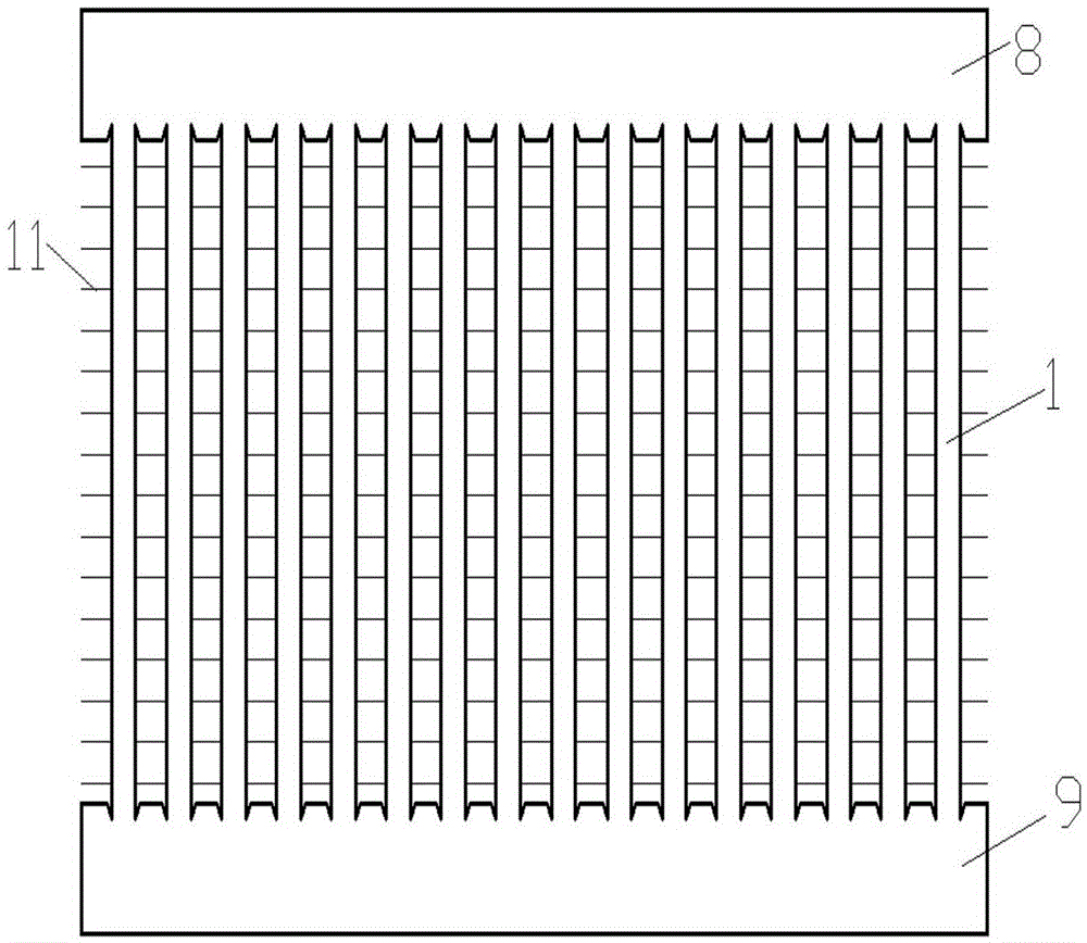
[0039] A heat exchanger such as figure 1 As shown, the heat exchanger includes two headers 8 and 9 and a heat exchange tube arranged between the two headers 8 and 9. External fins 11 are arranged between the heat exchange tubes. The heat exchanger may be widely used, for example, automobile heat exchangers, air conditioner heat exchangers, and the like.

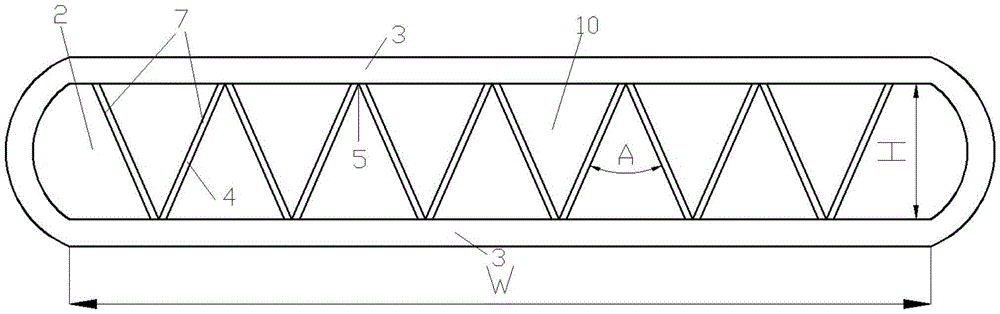
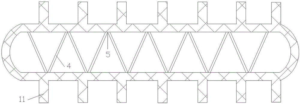
[0040] Such as figure 2 As shown, the heat exchange tube is a flat heat exchange tube, and includes a flat tube 1 and a fin 7. The flat tube 1 includes a tube wall 3 and a side wall 12 that are parallel to each other, and the side wall 12 connects the parallel tube walls. 3, a fluid channel 2 is formed between the side wall 12 and the parallel tube ...


PUM


Abstract

The invention provides a flat heat exchange pipe with communicated inner fins. The flat heat exchange pipe comprises a flat pipe body and the fins. The flat pipe body comprises parallel pipe walls, a fluid channel is formed between the parallel pipe walls, and the fins are arranged between the pipe walls. Each fin comprises an inclined part inclined to the pipe walls, the inclined parts are connected with the parallel pipe walls, the fluid channel is separated by the inclined parts into a plurality of small channels, the adjacent inclined parts are connected on the pipe walls, and triangles are formed by the adjacent inclined parts and the pipe walls. Communicating holes are formed in the inclined parts, and therefore the adjacent small channels are communicated. According to the flat heat exchange pipe, it is guaranteed that the adjacent small channels are communicated, the problem that the internal pressure of the flat pipe body is uneven under the condition of heat exchange is solved, the heat exchange efficiency is improved, and the service life is prolonged.

Description

Technical field [0001] The invention relates to a heat exchange tube used in a heat transfer device, in particular to a flat heat exchange tube connected by internal fins. Background technique [0002] Flat tubes have been widely used in automotive air conditioning units and residential or commercial air conditioning heat exchangers in recent years. A plurality of small channels are arranged inside the flat tube, and when in use, the heat exchange fluid flows through the plurality of channels in the flat tube. Because the flat tube has a large heat exchange area, the heat exchange effect can be greatly improved. [0003] The channels inside the flat tubes currently used are isolated from each other, so that each channel works independently from other channels when transferring heat. In this case, because the fluid distribution is uneven, the local pressure in the flat tube will be too large, and the pressure in the heat exchanger will be uneven, resulting in uneven internal heat ...

Claims


Application Information

Patent Timeline
Patent Type & Authority Applications(China)
IPC IPC(8): F28F1/40F28F1/42
CPCF28F1/40F28F1/42F28F2215/08
Inventor 杜文静陈岩
Owner SHANDONG UNIV
Why Eureka
Try Eureka