

Driving gear fixing and machining device
A driving gear and processing device technology, applied in gear tooth manufacturing devices, metal processing equipment, belts/chains/gears, etc., can solve problems such as affecting processing efficiency and cumbersome operations
- Summary
- Abstract
- Description
- Claims
- Application Information
AI Technical Summary
Problems solved by technology
Method used
Image

Examples
Embodiment Construction
[0014] The following is further described in detail through specific implementation methods:
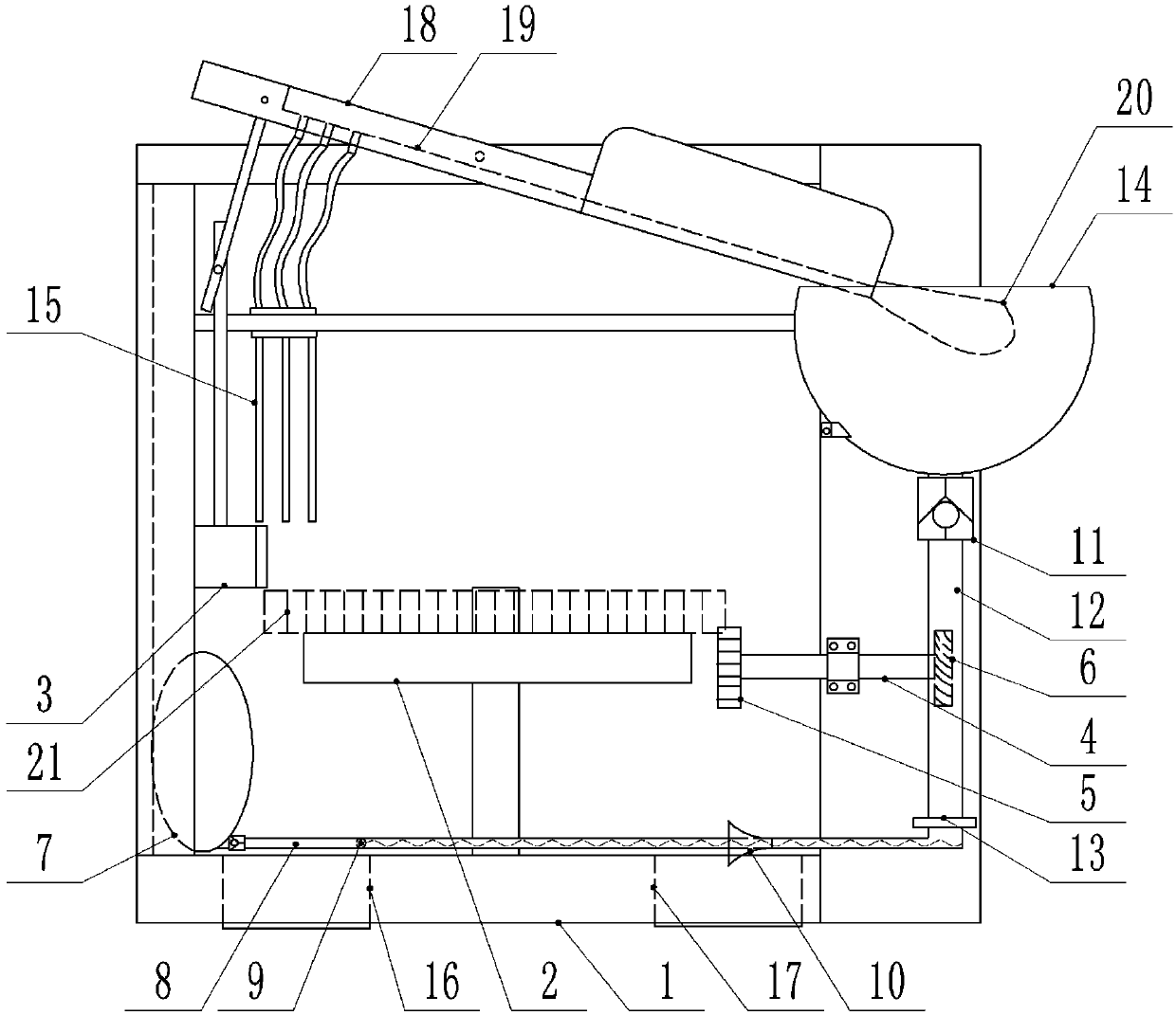
[0015] The reference signs in the accompanying drawings of the description include: base 1, rotary table 2, slider 3, drive rod 4, drive gear 5, turbine 6, air bag 7, inflation tube 8, magnetic beads 9, tapered sleeve 10, single Directional valve 11, air intake pipe 12, booster valve 13, water tank 14, spray pipe 15, waste liquid collection tank 16, waste residue collection tank 17, lever 18, drainage tank 19, water bucket 20, workpiece 21.
[0016] Example figure 1 Shown: the driving gear fixed processing device, including base 1, spray mechanism and recovery mechanism.
[0017] In this embodiment, in order to distinguish the gear to be processed from the driving gear 5 in the device structure, the gear to be processed is collectively referred to as the workpiece 21 .
[0018] The base 1 is used to connect the various parts of the installation equipment. The base 1 adopted in this...
PUM
 Abstract
Description
Claims
Application Information