Fluid pump and excitation element

A technology of fluid pumps and piezoelectric elements, which is applied to pump elements, components of pumping devices for elastic fluids, variable displacement pump components, etc., can solve the problems of low output capacity, low reliability, and high cost, and achieve Effects of increasing output flow and output pressure, improving output performance, and high output flow

Pending Publication Date: 2019-04-30
常州威图流体科技有限公司
View PDF0 Cites 1 Cited by
  • Summary
  • Abstract
  • Description
  • Claims
  • Application Information

AI Technical Summary

Problems solved by technology

[0005] The purpose of the present invention is to provide a compact and high output capacity solution in order to solve the problems existing in the prior art such as complex structure, high cost, high noise or low reliability, insufficient fluid delivery or insufficient pressure, and low output capacity. micro fluid pump

Method used


Image

  • Fluid pump and excitation element
  • Fluid pump and excitation element
  • Fluid pump and excitation element

Examples


Embodiment 1

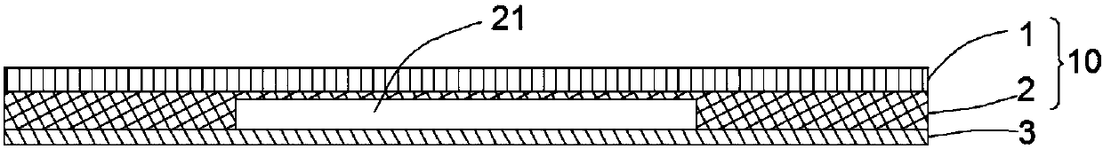
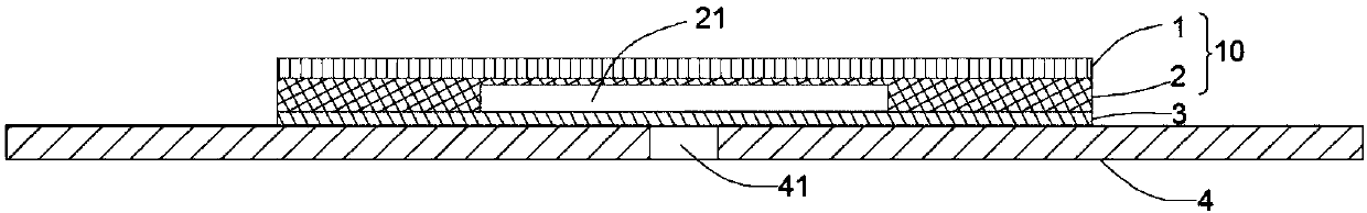
[0037] like figure 1 As shown, the fluid pump of this embodiment includes a piezoelectric vibrator 10, a vibrating diaphragm 3, and a surface 4, wherein the piezoelectric vibrator 10 includes a vibrating substrate 2 and a piezoelectric element 1 disposed on one side of the vibrating substrate 2, and the piezoelectric element 1 The piezoelectric vibrator 10 is formed centrally with the vibrating substrate 2 and bonded together to form a piezoelectric vibrator 10. The piezoelectric vibrator 10 can generate bending vibration from its central part to the peripheral part. The vibrating substrate 2 is made of metal such as stainless steel or phosphor bronze. Electrode films are formed on the upper and lower surfaces of the electric element 1, respectively. The electrodes on the lower surface are electrically connected to the vibrating substrate and form capacitive coupling. The electrodes on the upper surface are connected with conductor lines, and the conductor lines are connected t...

Embodiment 2

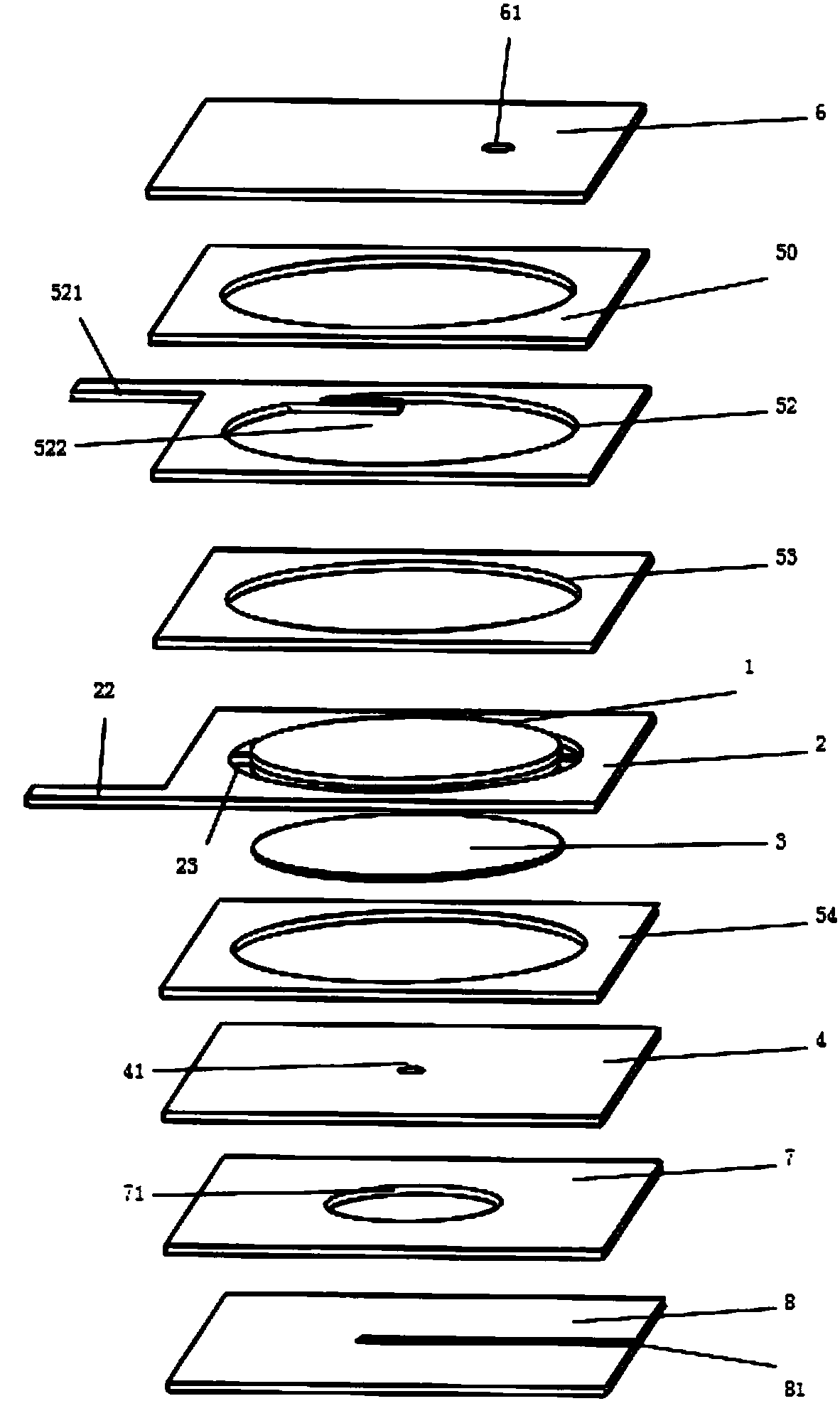
[0051] like Figure 5 As shown, the fluid pump of this embodiment is basically the same as that of Embodiment 1, the difference is that the fluid pump also includes a support plate 5 and an upper cover plate 6, the support plate 5 is arranged on the plane portion 4, and the two are hermetically connected, and the upper cover The plate 6 is arranged on the support plate 5, and the upper cover plate 6 and the support plate 5 are also connected in a sealed manner, thereby forming a cavity 51, wherein a through hole 61 is provided at the center of the upper cover plate 6 or other positions, through which The through hole 61 communicates with the outside atmosphere.

[0052] When not driven, the excitation element is relatively arranged on the plane part 4 in a contact manner. When driven by a power source, according to the principle described in Embodiment 1, the fluid is sucked through the central vent hole 41, and then the sucked fluid is discharged through the through hole 61....

Embodiment 3

[0054] like Figure 6 and Figure 7 Shown are the structural exploded view and cross-sectional view of the fluid pump of the third embodiment respectively. This embodiment is basically the same as the first embodiment, the difference is that the structure of the vibrating base plate 2 is improved, by Figure 6 It can be seen that the vibrating substrate 2 includes a central vibrating area, surrounding supporting parts, elastic connecting parts 23 and first wire welding parts 22 . Wherein, the elastic connecting part 23 is set as an elastic structure with a small elastic coefficient, so that the middle vibration region is softly supported by the surrounding support parts, so it can be considered that the elastic support will not hinder the bending vibration of the middle vibration region, that is, the vibration region is substantially in the A state of being unconstrained.

[0055] In addition, the fluid pump of this embodiment also includes an upper cover plate 6 , a first s...


PUM


Abstract

The invention belongs to the technical field of fluid delivery, and relates to a fluid pump and an excitation element. The fluid pump comprises a piezoelectric vibrator, a vibration diaphragm and a planar part, wherein the piezoelectric vibrator comprises a vibration substrate and a piezoelectric element which is arranged on one side of the vibration substrate; the vibration diaphragm is arrangedon one side of the vibration substrate; the vibration diaphragm is arranged on the other side of the vibration substrate, and one side, close to the vibration diaphragm, of the vibration substrate isprovided with a sunk cavity; and the planar part is arranged on one side, far away from the vibration substrate, of the vibration diaphragm in a manner of being close to and opposite to the vibrationdiaphragm, and at least one vent hole is formed in the area, opposite to the sunk cavity, of the plane part; and a certain frequency of alternating voltage is applied to the piezoelectric element, thevibration substrate is bent and deformed to enable the vibration diaphragm to generate resonance, the vibration diaphragm is bent and deformed along with the vibration substrate in the same direction, and then the fluid pump sucks the fluid from the vent hole and is discharged from the circumferential direction of the vent hole. According to the fluid pump and the excitation element, higher output pressure and output flow can be obtained, great market value is achieved, and the fluid pump and the excitation element is worthy of popularization.

Description

technical field [0001] The invention belongs to the technical field of fluid delivery equipment, and in particular relates to a fluid pump. Background technique [0002] Microfluidic pumps have a wide range of application requirements in the fields of medicine and biology, fine chemicals, aerospace, and micro-electromechanical systems. Today's electronic products with application goals usually have a trend of miniaturization, which also requires microfluid pumps to be more miniaturized while ensuring their output capacity (output pressure and output flow) or to improve their performance without being oversized. output capacity. [0003] Current gas micropumps mainly include electromagnetic diaphragm pumps driven by motor cam mechanisms, piezoelectric diaphragm pumps driven by piezoelectric vibrators, and micropumps using squeeze film effects. A piezoelectric pump is a diaphragm pump in which an alternating voltage is applied to a piezoelectric element to bend and deform th...

Claims


Application Information

Patent Timeline
Patent Type & Authority Applications(China)
IPC IPC(8): F04B43/04F04B53/00
CPCF04B43/046F04B53/00
Inventor 周京京钟德坤焦会萌韦东东吴垠
Owner 常州威图流体科技有限公司
Why Eureka
Try Eureka