Apparatus for marking the operation of an induction coil by illumination

a technology for induction coils and apparatuses, applied in the direction of lighting and heating apparatus, domestic cooling apparatus, furniture, etc., can solve the problems of increasing the overall height, complicated electrical connection of illumination means,

Inactive Publication Date: 2004-12-07
E G O ELEKTRO GERAETEBAU GMBH
View PDF11 Cites 18 Cited by
  • Summary
  • Abstract
  • Description
  • Claims
  • Application Information

AI Technical Summary

Benefits of technology

In order to consume minimum energy, LEDs are advantageously used as the illumination means. Particular advantage is gained through LEDs, which are heat-resistant up to at least 100.o slashed. C. In this way operation under a glass ceramic cooking field is in most cases easily possible without excess temperature problems. Through the alternative use of glow lamps, excess temperature problems can be completely avoided.
If the supports of the apparatuses are circular ring sectors, e.g. 1 / 3 circular ring sectors, a fitting thereof is easily possible. This can e.g. be such that the induction coil, particularly with several induction coils together, is secured to a base holder and at least one support is fixed to the latter. Fixing can e.g. take place by adhesion, particularly using two-sided foam adhesive strips.

Problems solved by technology

However, the electrical connection of the illumination means is complicated.
As a result of the location below the induction coil there is an increase in the overall height, which is considered disadvantageous.

Method used


Image

  • Apparatus for marking the operation of an induction coil by illumination
  • Apparatus for marking the operation of an induction coil by illumination

Examples


Embodiment Construction

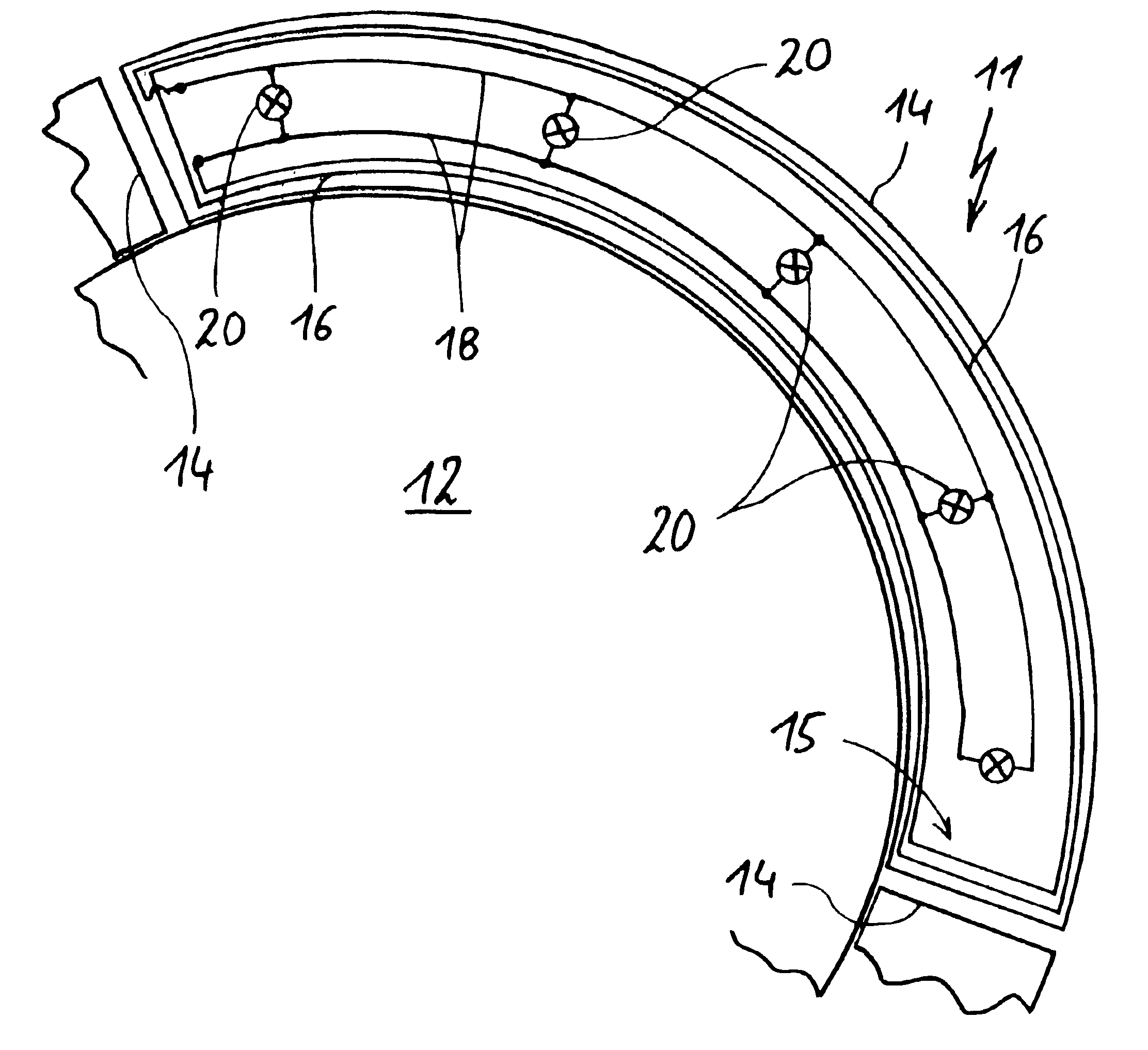
FIG. 1 shows a possible construction of an illuminating apparatus 11, which has a circular ring sector shape and in this case a third of a circle. The illuminating apparatus 11 is positioned at a limited distance from the outer edge of an induction coil 12. As shown, to the left and right are connected to the lighting apparatus 11 preferably identically constructed, further lighting apparatuses, so as to form a complete circle around the induction coil 12.

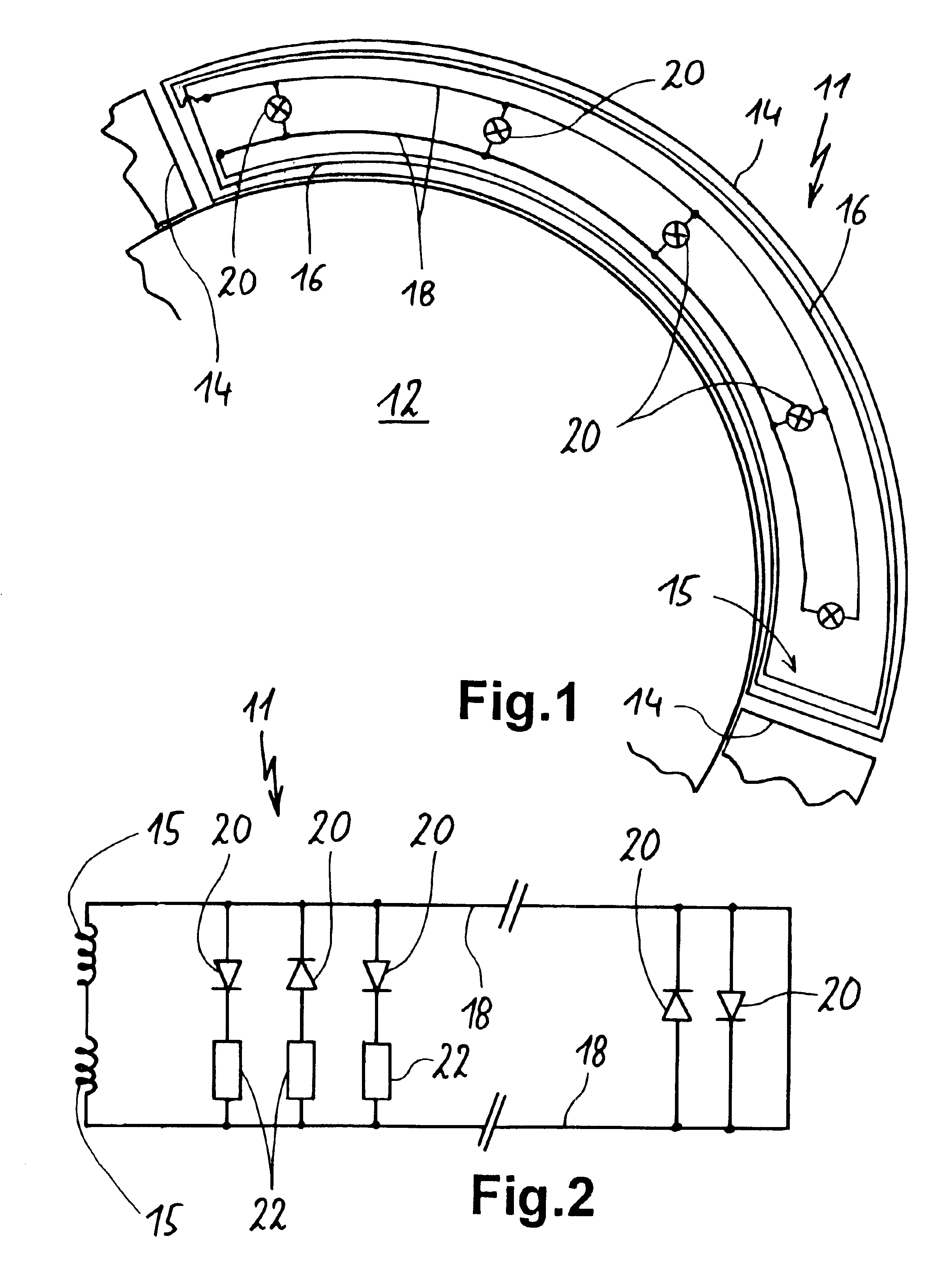
The illuminating apparatus 11 comprises a printed circuit board 14. On the latter is applied the coil 15 in the form whereby the circumferential coil turns 16 are formed by corresponding conducting tracks. A coil 15 with two turns 16 is shown to facilitate viewing. In practice more turns are preferred, e.g. seven or eight. As can be seen in the left-hand, upper area of the printed circuit board 14, a track overlap is necessary. This is diagrammatically illustrated by a bridge. In practice this can be brought about by a separate com...


PUM


Abstract

An illuminating apparatus for an induction coil of an induction cooking field is in the form of a 1 / 3 circular ring segment and carries conducting tracks, which form turns of a coil, which is connected to several LEDs. During induction coil operation an alternating voltage is induced in the coil and consequently the LEDs are supplied. With such an illuminating apparatus it is possible without additional wiring expenditure to illuminate an induction coil under a glass ceramic cooking field.

Description

FIELD OF APPLICATION AND PRIOR ARTThe invention relates to an apparatus for marking the operation and / or the position of an induction coil of an inductive cooking field by illumination or illuminated marking. Furthermore, the invention relates to an inductive heating device with such an apparatus.Induction coils of an inductive cooking field can be located beneath a glass ceramic plate on which is placed a corresponding saucepan. Below this plate is located the induction coil and transmits energy into the bottom of the saucepan for heating purposes.Such as is e.g. the case with radiant heaters, in many cases it is here desirable to have an optical indication of the operation or position of the heating in the vicinity of the latter. It is possible to place beneath an induction coil illumination means and by means of laterally extracted light guides to mark the induction coil by illumination. However, the electrical connection of the illumination means is complicated. As a result of t...

Claims


Application Information

Patent Timeline
Patent Type & Authority Patents(United States)
IPC IPC(8): H05B6/12
CPCH05B6/1218
Inventor BOEGEL, JOERGSTOEFFLER, MICHAELSCHILLING, WILFRIED
Owner E G O ELEKTRO GERAETEBAU GMBH
Why Eureka
Try Eureka