
Driving apparatus and image formation apparatus using the driving apparatus

a technology of driving apparatus and driving apparatus, which is applied in the direction of printing mechanism, gears, instruments, etc., can solve the problems of unable to cope with the speed fluctuation caused by the mesh component of each gear, the application of flywheel technique from the viewpoint of miniaturization, and the cost of image formation apparatus

Inactive Publication Date: 2004-12-07
FUJIFILM BUSINESS INNOVATION CORP
View PDF7 Cites 31 Cited by
  • Summary
  • Abstract
  • Description
  • Claims
  • Application Information

AI Technical Summary

Benefits of technology

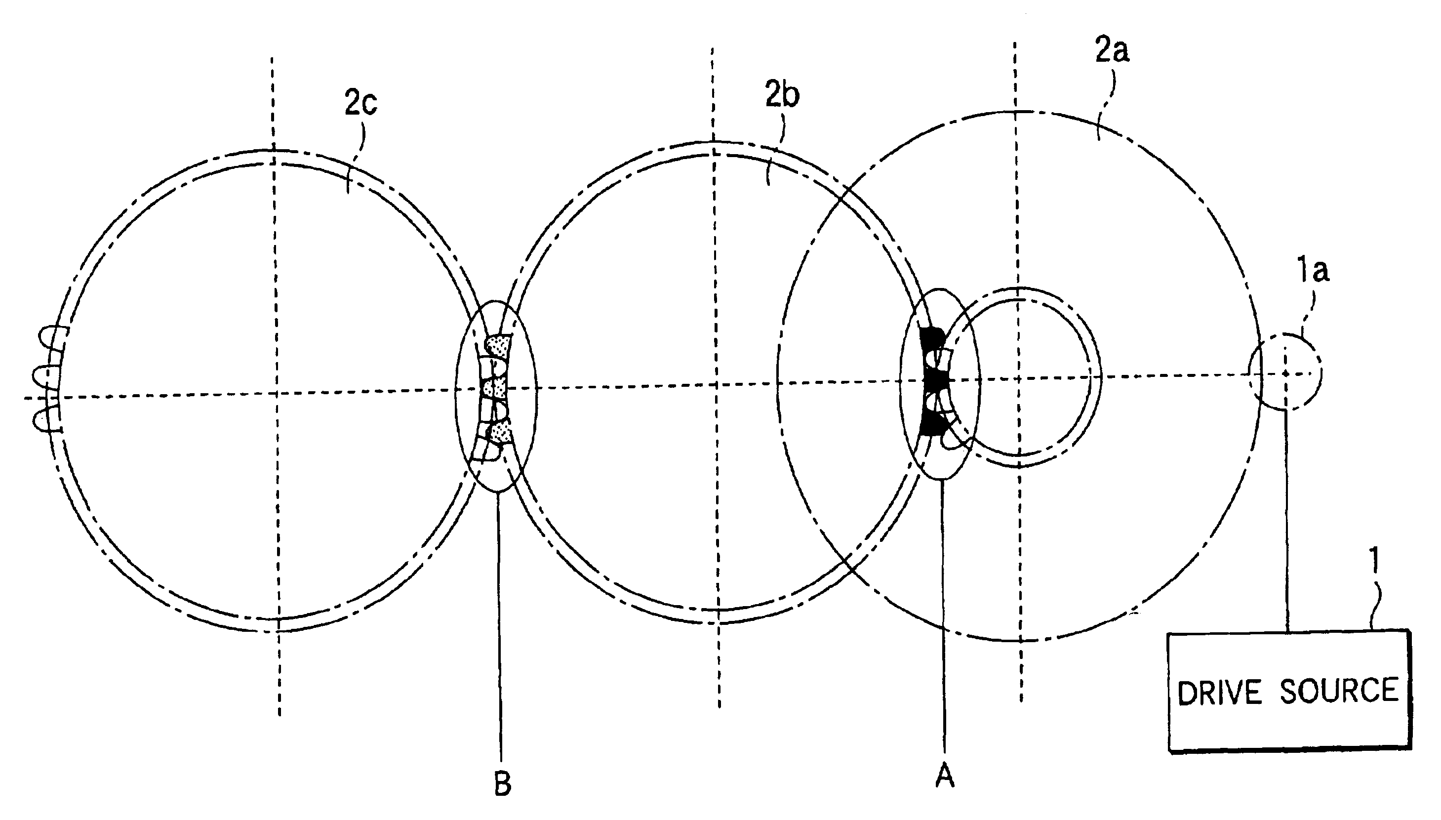
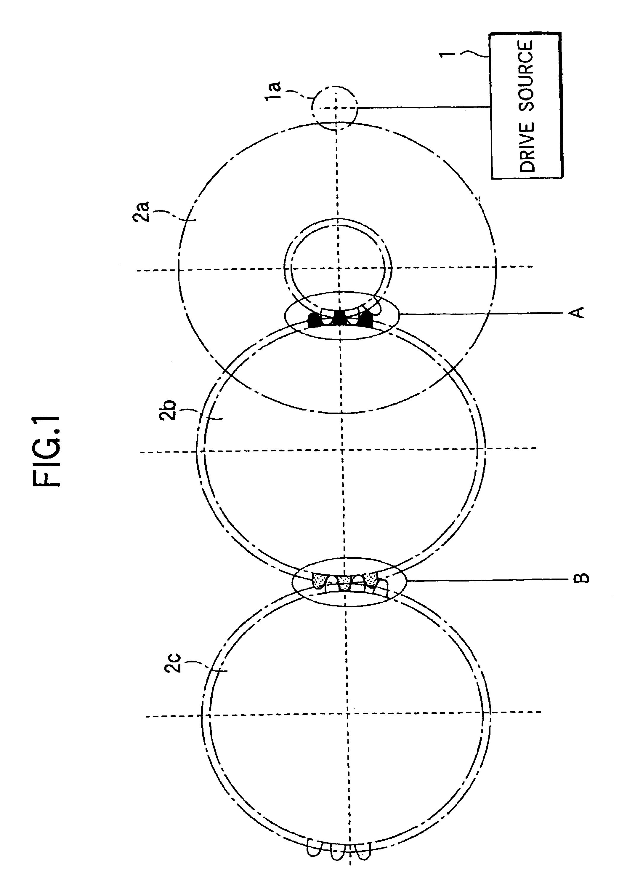
The invention relates to a driving apparatus for an image formation apparatus such as a copier or printer. The driving apparatus uses a multiple-stage gear train and a flywheel to prevent vibration and speed fluctuation caused by gear eccentricity and motor speed fluctuation. However, the existing techniques for reducing speed fluctuation caused by gear mesh frequency have limitations such as increased parts and size of the apparatus. The invention aims to provide a driving apparatus that can effectively prevent speed fluctuation without increasing the size of the apparatus.

Problems solved by technology

Thus, for example, to apply a driving apparatus of a multiple-stage gear train to a tandem image formation apparatus, etc., it is extremely difficult to apply the flywheel technique from the viewpoints of miniaturizing and making cheaper the image formation apparatus.
However, this type may cope with speed fluctuation caused by the eccentricity component of each gear, but still cannot cope with speed fluctuation caused by the mesh component of each gear.
In this technique, it may be possible to roughly cancel fluctuation (color shift) of the one-revolution period of the photoconductor drum and an intermediate transfer body, caused by the eccentricity of the gears for driving the photoconductor drum and the intermediate transfer body, but an image defect (banding) caused by expansion or contraction of an image caused by the speed fluctuation of gear mesh frequency is not remedied at all; this is a technical problem.
Because of the configuration of the helical gear, thrust easily occurs and if looseness is contained in the axial direction of the helical gear, there is a possibility that the speed fluctuation phase of the mesh frequency may change, causing speed fluctuation of the target gear 2c to occur.

Method used


Image

  • Driving apparatus and image formation apparatus using the driving apparatus
  • Driving apparatus and image formation apparatus using the driving apparatus
  • Driving apparatus and image formation apparatus using the driving apparatus

Examples


second example

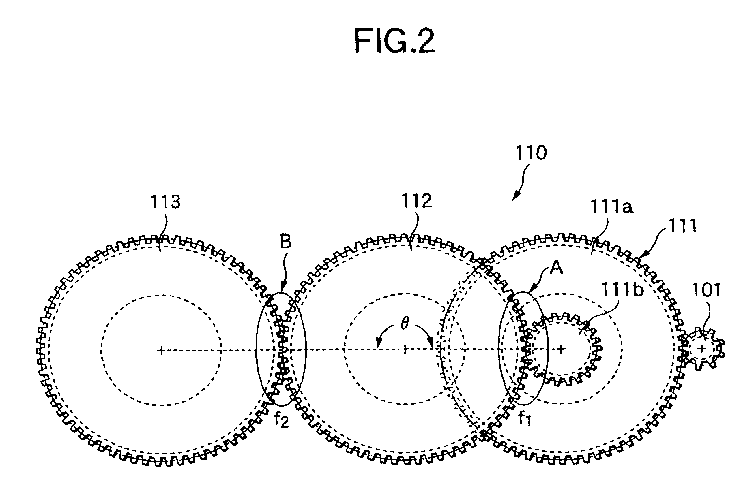
As shown in FIG. 26(a), a second example is a driving apparatus having a three-stage gear train including gears G1 (Gear-1) to G3 (Gear-3) meshing with a motor shaft gear 131, wherein the first gear G1 is a two-step gear, the second gear G2 as the center meshes with the first gear G1 at mesh point 1 and the third gear G3 at mesh point 2, and the third gear G3 is driven with deceleration.

In the example, speed fluctuation of mesh frequency is represented as follows:

.DELTA.V(t)=.alpha.1 Sin(.omega.t+.beta.1)+.alpha.2 Sin(.omega.t+.beta.2)+.alpha.3 Sin(.omega.t+.beta.3)

where

.alpha.1: Speed fluctuation amplitude of gear G1 (0-pk)

.alpha.2: Speed fluctuation amplitude occurring due to mesh of gears G1 and G2 (0-pk)

.alpha.3: Speed fluctuation amplitude occurring due to mesh of gears G2 and G3 (0-pk)

.beta.1: Speed fluctuation phase of gear G1

.beta.2: Speed fluctuation phase occurring due to mesh of gears G1 and G2

.beta.3: Speed fluctuation phase occurring due to mesh of gears G2 and G3

The sp...

third example

As shown in FIG. 32(a), a third example is a driving apparatus having a three-stage gear train including gears G1 (Gear-1) to G3 (Gear-3) meshing with a motor shaft gear 131, wherein the first gear G1 is a two-step gear, the second gear G2 as the center meshes with the first gear G1 at mesh point 1 and the third gear G3 at mesh point 2, and the third gear G3 is driven at increased speed.

The speed fluctuation amplitude .alpha. and speed fluctuation phase .beta. of each of the gears G1 to G3 and the speed fluctuation amplitude a and phase .beta. of addition component at mesh 1, 2 were set as in FIG. 32(b).

Angle between mesh points, .theta., is represented as follows:

.theta.=n.times..theta.p+0.5.times..theta.p

In the example, the speed fluctuation ratios of the gears G1 to G3 and meshes 1 and 2 indicate a similar trend to that in FIG. 25, and the relationship between gear G1 phase direction amplitudes and phase orthogonal direction amplitudes orthogonal thereto, of the gears G1 to G3 an...

fourth example

In a fourth example, using the driving apparatus according to the fifth embodiment (speed increasing mode), motion quality (MQ) of a model 1 specific gear in which motor shaft gear, IDT2 drive gear, IDT1 drive gear, and photoconductor drum drive gear had a crest / trough / trough mesh transmission technique in mesh phase of motor shaft gear / IDT2 drive gear / IDT1 drive gear / photoconductor drum drive gear and motion quality (MQ) of a model 2 specific gear in which in which motor shaft gear, IDT2 drive gear, IDT1 drive gear, and photoconductor drum drive gear had a crest / trough / crest mesh transmission technique were measured.

FIG. 33(a) shows the speed fluctuation ratios of IDT2 drive gear (in the figure, IDT2) / IDT1 drive gear (in the figure, IDT1) / photoconductor drum drive gear (in the figure, Drum) of the model 1 specification gear. FIG. 33(b) shows the speed fluctuation ratios at mesh 1 (IDT1-IDT2) and mesh 2 (DrumIDT1).

On the other hand, FIG. 34(a) shows the speed fluctuation ratios of I...


PUM


Abstract

A driving apparatus transmits a driving force from a drive source to a driven body via a multiple-stage gear train (including, for example, gears). In the multiple-stage gear train, the speed fluctuation phase of a mesh frequency occurring at each mesh point of the gear train including the gears to a target gear is set in a range in which the speed fluctuation amplitude of the target gear positioned downstream at the third stage or later is equal to or less than the speed fluctuation amplitude of the immediately preceding mesh gear positioned upstream. The invention also applies to an image formation apparatus using the drive as a drive of a driven body.

Description

The present disclosure relates to the subject matter contained in Japanese Patent Application No.2001-381884 filed on Dec. 14, 2001 and Japanese Patent Application No.2002-248548 filed on Aug. 28, 2002, which are incorporated herein by reference in its entirety.1. Field of the InventionThis invention relates to a driving apparatus used with an image formation apparatus, such as a copier or a printer, and in particular to improvements in a driving apparatus for transmitting a driving force from a drive source to a driven body via a multiple-stage gear train and an image formation apparatus using the driving apparatus.2. Description of the Related ArtGenerally, as a technique of driving a driven body such as a photoconductor drum or an intermediate transfer body in an image formation apparatus such as a copier or a printer, a driving apparatus for transmitting a driving force from a drive source such as a motor to a driven body with a multiple-stage gear train (a gear train comprising...

Claims


Application Information

Patent Timeline
Patent Type & Authority Patents(United States)
IPC IPC(8): F16H57/12F16H57/00G03G15/01G03G15/00B41J19/76F16C13/00F16H1/20G03G15/16G03G21/00
CPCF16H57/12G03G15/757G03G15/0194Y10T74/19G03G2215/0119
Inventor RYUZAKI, TAKAHIKOHOKARI, NORIONISHIKAWA, SATORUKIBAYASHI, SUSUMUMITAMURA, YOSHIHIKOHANZAWA, TOKUAKIYOSHIHARA, MICHIAKI
Owner FUJIFILM BUSINESS INNOVATION CORP
Learn More