Universal crimping connector

a connector and universal technology, applied in the direction of connection, electrical apparatus, coupling device connection, etc., can solve the problems of real difficulty in reaching a compromise, difficult to insert the cable into the connector sleeve, and impedance problem in the higher frequency rang

Inactive Publication Date: 2004-12-14
PPC BROADBAND INC
View PDF24 Cites 90 Cited by
  • Summary
  • Abstract
  • Description
  • Claims
  • Application Information

AI Technical Summary

Benefits of technology

A further object of the present invention is to provide for a novel and improved cable connector with pre-assembled crimping ring which will effect sealed engagement between the connector and cable in a minimum number of steps and simplified manner.

Problems solved by technology

A problem which has confronted the cable T.V. industry for years has been to provide a single connector size which can accommodate a plurality of different-sized cables.
At the same time, the degree of compression must not be so great as to cause the inner sleeve to collapse or be damaged or otherwise result in an impedance problem in the higher frequency ranges.
Especially in larger cables, there is real difficulty in reaching a compromise between the optimum inner diameter of the crimping ring which will permit the cable to be easily inserted into the connector sleeve and the size necessary to effect a good crimp.
Since the crimping is most important to assure a good connection, typically the inner diameter of the crimping ring is such that it is very difficult to insert the cable into the connector sleeve.
This requires manual dexterity on the part of the installer and, after a day of making connections, can be extremely time-consuming, difficult and very tiring.

Method used


Image

  • Universal crimping connector
  • Universal crimping connector
  • Universal crimping connector

Examples


Embodiment Construction

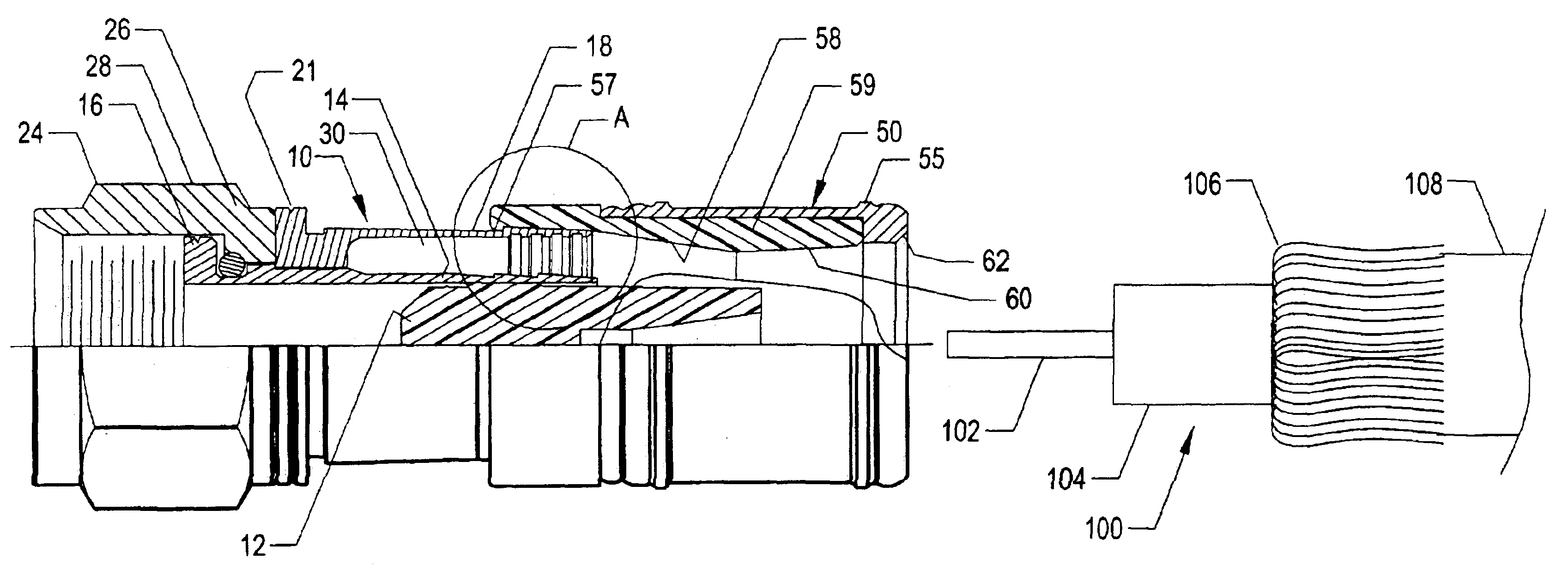
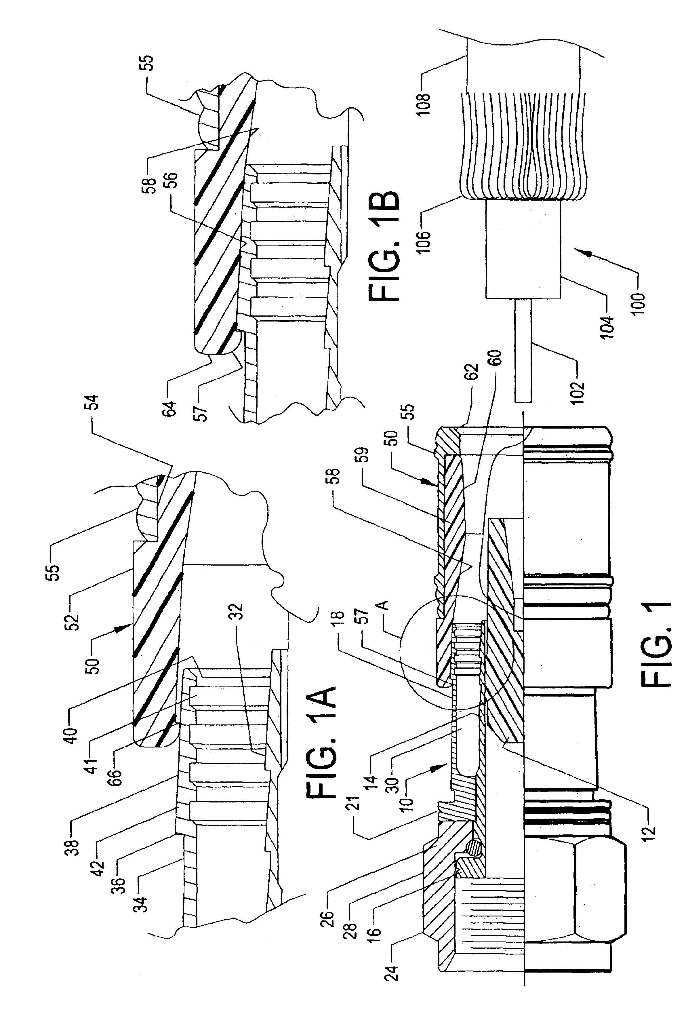
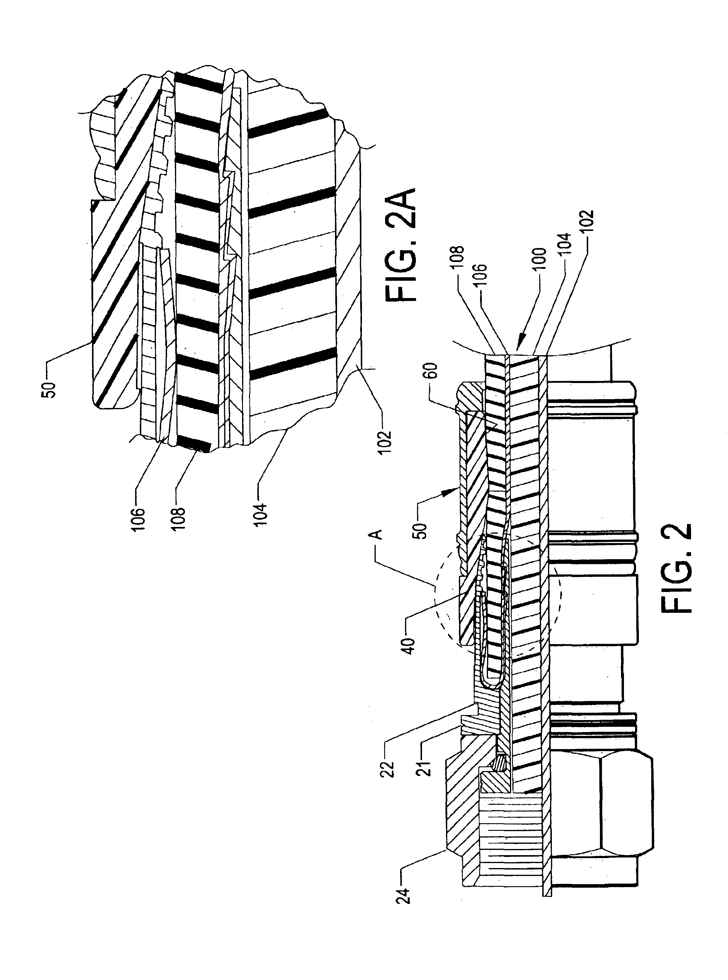
Referring in detail to the drawings, there is illustrated in FIGS. 1 to 3 an end connector 10 which is adapted for connecting a standard coaxial cable 100 to a television terminal. FIG. 1 illustrates the connector 10 in the open or preassembled position with a standard coaxial cable 100 aligned with a starter guide 12 which aids in aligning the cable for insertion into the connector as illustrated in FIG. 2. The starter guide 12 is illustrated and described in more detail in U.S. Pat. No. 6,352,408 for CABLE TV END CONNECTOR STARTER GUIDE and is incorporated by reference herein. A crimping ring 50 is preassembled onto one end of the connector 10 prior to insertion of the cable 100.

The end connector 10 is broadly made up of an inner concentric sleeve 14 having an external shoulder 16 at its forward end, and an outer concentric sleeve shoulder has an external shoulder 21 and an external groove 22. A threaded fastener 24 has a rearward end 26 which is interpositioned between the should...


PUM


Abstract

A coaxial cable TV connector is made up of one or more crimping members having inner tapered surface portions which are preassembled onto a crimpable sleeve member of a connector body, the sleeve having an external tapered portion into which the coaxial cable is inserted so that the crimping ring(s) can be preassembled onto the sleeve and axially advanced to cause inward radial deformation of the sleeve into sealed engagement with an outer surface of the coaxial cable, and each size of connector assembly is conformable for use with more than one size of cable.

Description

BACKGROUND AND FIELD OF INVENTIONThis invention relates to cable connectors; and more particularly relates to a novel and improved compression-type connector in which a single size connector is capable of accommodating different cable sizes.A problem which has confronted the cable T.V. industry for years has been to provide a single connector size which can accommodate a plurality of different-sized cables. The standard coaxial cable is made up of a center conductor, insulated layer surrounding the conductor, foil layer, braided layer and outer jacket. This is a typical dual shield cable having a single braided layer which is the outer conductor. Depending upon the specific application and frequencies being transmitted through the cable, it is necessary to modify the thickness of the braided layers, and consequently there are dual-shield, tri-shield and quad-shield cables. In general, the higher the frequency the shorter the wavelength and therefore requires more shielding to preven...

Claims


Application Information

Patent Timeline
Patent Type & Authority Patents(United States)
IPC IPC(8): H01R13/00H01R9/05H01R13/646
CPCH01R9/0518H01R2103/00
Inventor HOLLIDAY, RANDALL A.
Owner PPC BROADBAND INC
Why Eureka
Try Eureka