
Microwave field effect transistor structure

a micro-field effect transistor and transistor structure technology, applied in the direction of semiconductor/solid-state device details, semiconductor devices, electrical apparatus, etc., can solve the problems of inductance and capacitance limiting the performance of the multiple conductive plug structure of the lateral rf mos devi

Inactive Publication Date: 2004-12-14
QORVO US INC
View PDF7 Cites 69 Cited by
  • Summary
  • Abstract
  • Description
  • Claims
  • Application Information

AI Technical Summary

Problems solved by technology

As processing technology improved, in the early 1970's a number of MOSFET vertical structures began to challenge the dominance of the BJT at the lower RF frequencies, trading the cost of the large silicon area, necessary to provide the current capability in MOSFETs, for the cost of simple processing.
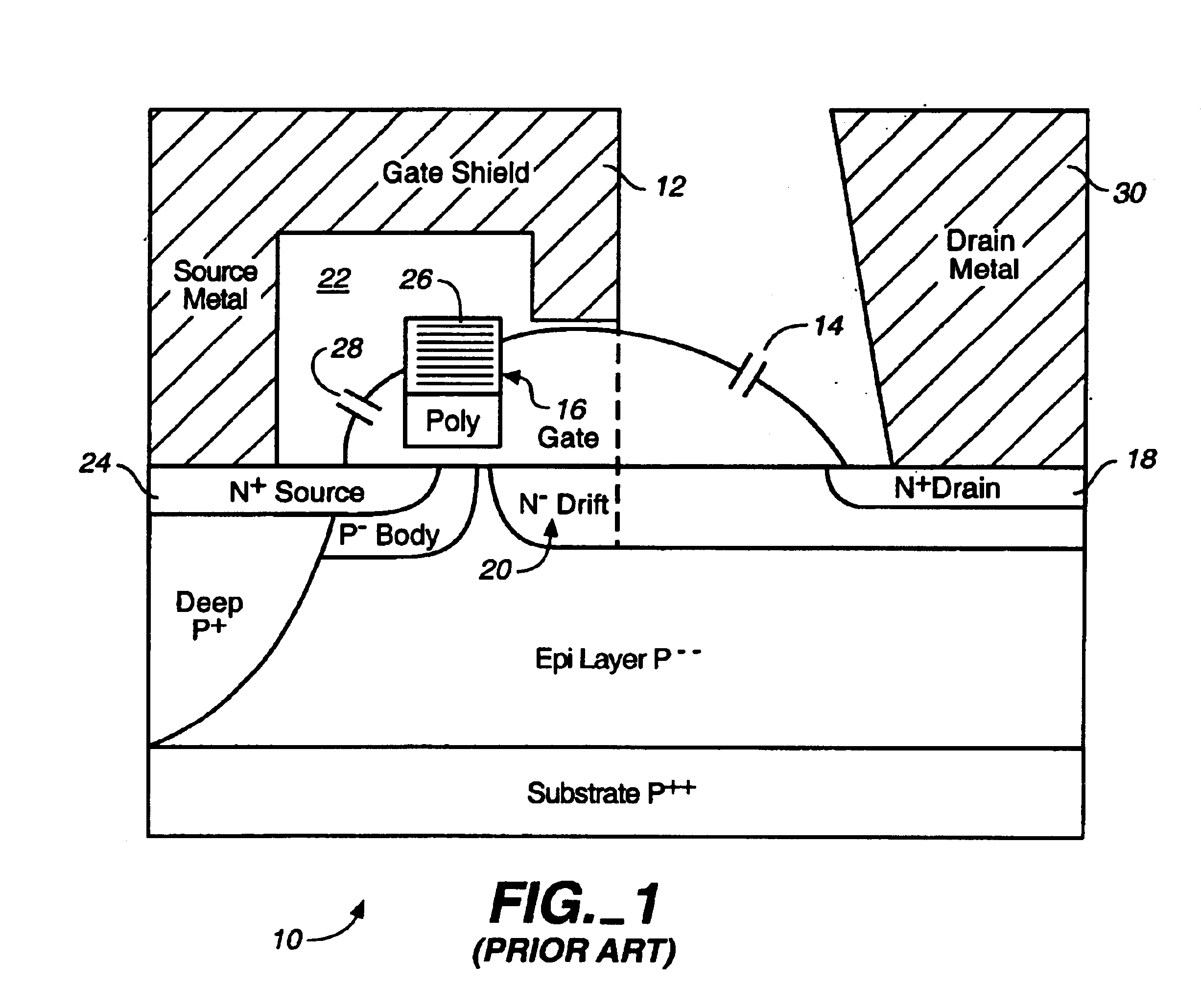
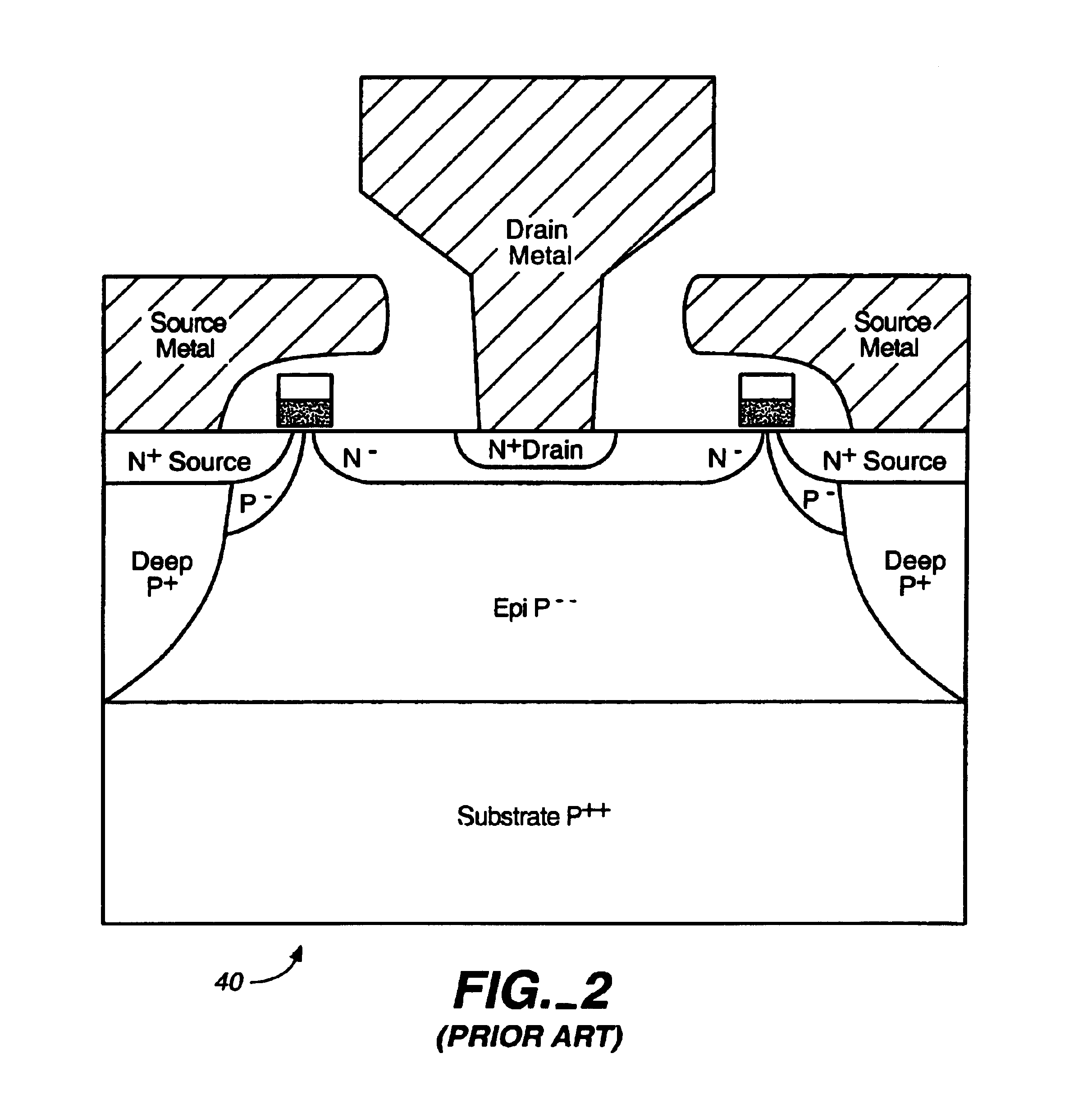
As the applications for wireless communications move up in the frequency spectrum, parasitic resistances, capacitances and inductances limit the performance of the multiple conductive plug structure for lateral RF MOS devices, as described in the '104 patent.

Method used


Image

  • Microwave field effect transistor structure
  • Microwave field effect transistor structure
  • Microwave field effect transistor structure

Examples


Embodiment Construction

.

Reference will now be made in detail to the preferred embodiments of the invention, examples of which are illustrated in the accompanying drawings. While the invention will be described in conjunction with the preferred embodiments, it will be understood that they are not intended to limit the invention to these embodiments. On the contrary, the invention is intended to cover alternatives, modifications and equivalents that may be included within the spirit and scope of the invention as defined by the appended claims. Furthermore, in the following detailed description of the present invention, numerous specific details are set forth in order to provide a thorough understanding of the present invention. However, it will be obvious to one of ordinary skill in the art that the present invention may be practiced without these specific details. In other instances, well known methods, procedures, components, and circuits have not been described in detail as not to unnecessarily obscure a...


PUM


Abstract

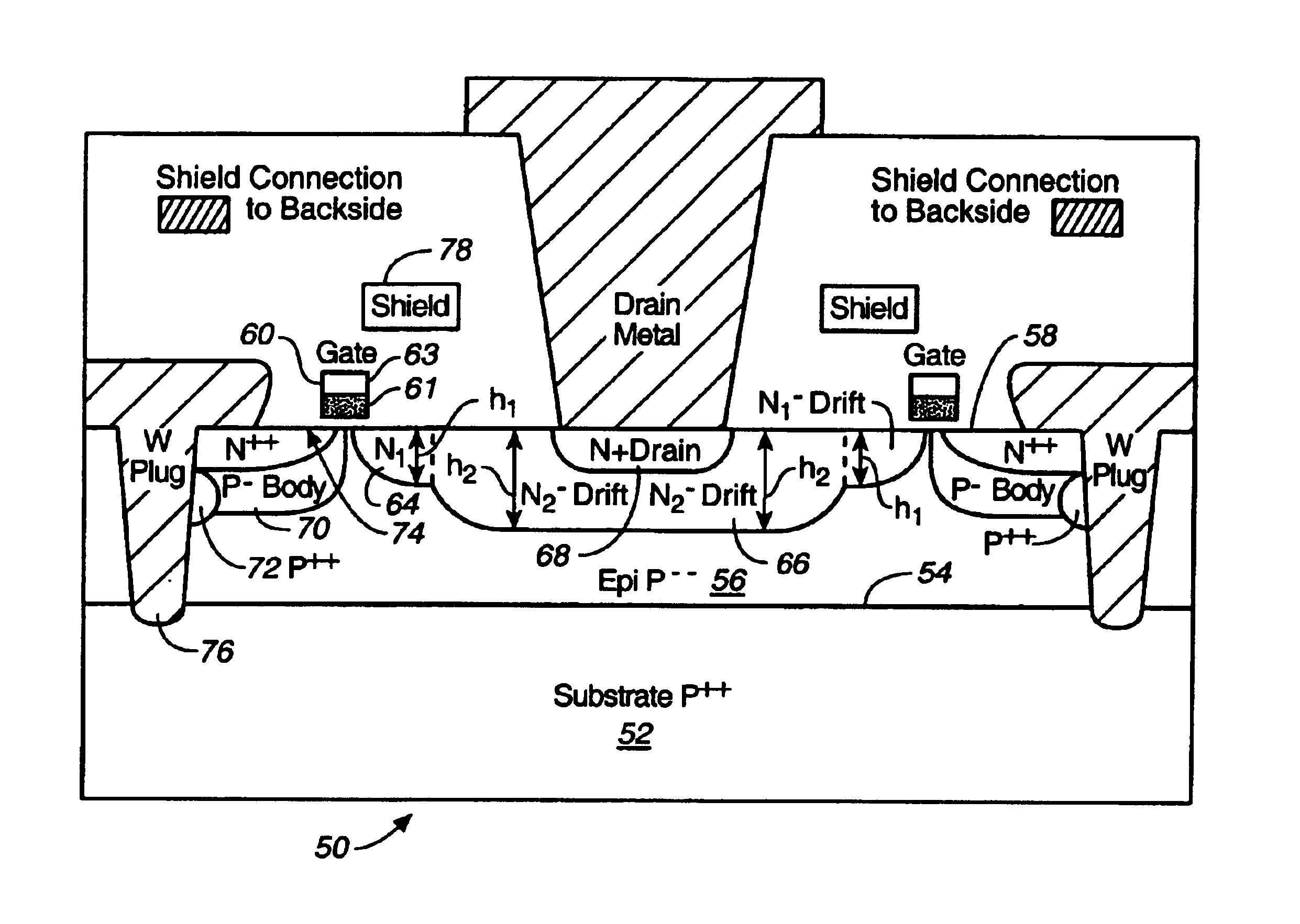
A microwave transistor structure comprising: (1) a substrate having a top surface; (2) a silicon semiconductor material of a first conductivity type; (3) a conductive gate; (4) a channel region of a second conductivity type; (5) a drain region of the second conductivity type; (6) a body of the first conductivity type; (7) a source region of the second conductivity type; (8) a shield plate region formed on the top surface of the silicon semiconductor material over a portion of the channel region, wherein the shield plate is adjacent and parallel to the drain region, and to the conductive gate region; and (9) a conductive plug region formed in the body region of the silicon semiconductor material, wherein the conductive plug region connects a lateral surface of the body region to the top surface of the substrate.

Description

1. Field of the InventionThe present invention is in the field of microwave field effect transistors, and more specifically, is in the field of a new Silicon power LDMOS structure optimized for operation above 3 GHz, for use in wireless communication applications.2. Discussion of the Prior ArtIn the prior art, power high frequency devices have been built using a variety of semiconductor technologies. For a long time the preferred vehicle for their realization has been the NPN bipolar junction transistor (BJT). Its primary advantage was the achievable high intrinsic transconductance (gm) that permitted the fabrication of high power devices utilizing small silicon areas.As processing technology improved, in the early 1970's a number of MOSFET vertical structures began to challenge the dominance of the BJT at the lower RF frequencies, trading the cost of the large silicon area, necessary to provide the current capability in MOSFETs, for the cost of simple processing. The advantages tha...

Claims


Application Information

Patent Timeline
Patent Type & Authority Patents(United States)
IPC IPC(8): H01L29/66H01L29/78H01L29/417H01L29/08H01L29/02H01L29/40H01L29/06
CPCH01L29/7835H01L29/0847H01L29/402H01L29/41766H01L2924/0002H01L2924/00
Inventor D'ANNA, PABLOJOHNSON, JOSEPH H.
Owner QORVO US INC
Learn More