Pneumatic bilge liquid removal system and method therefor

a technology of bilge liquid and pump, which is applied in the direction of hulls, non-positive displacement pumps, vessel construction, etc., can solve the problems of large residual bilge water, small pumps that are not as helpful in keeping vessels afloat, and fouling the pump

Active Publication Date: 2005-01-04
BAURLEY ALFRED RUDOLPH
View PDF19 Cites 11 Cited by
  • Summary
  • Abstract
  • Description
  • Claims
  • Application Information

AI Technical Summary

Benefits of technology

It is an object of the present invention to provide a pneumatic bilge liquid removal sys

Problems solved by technology

However, despite its great capacity, it leaves a large amount of residual bilge water after it has completed a cycle.
Although smaller sized pumps provide lower residual water levels, smaller pumps would not be as helpful in keeping vessels afloat in the event of an emergency.
Moreover, the centrifugal, vertical shaft impeller pumps need to reside in the bilge water, which over time, foul the pump.
Lobe impeller pumps are typically mounted ab

Method used


Image

  • Pneumatic bilge liquid removal system and method therefor
  • Pneumatic bilge liquid removal system and method therefor
  • Pneumatic bilge liquid removal system and method therefor

Examples


Embodiment Construction

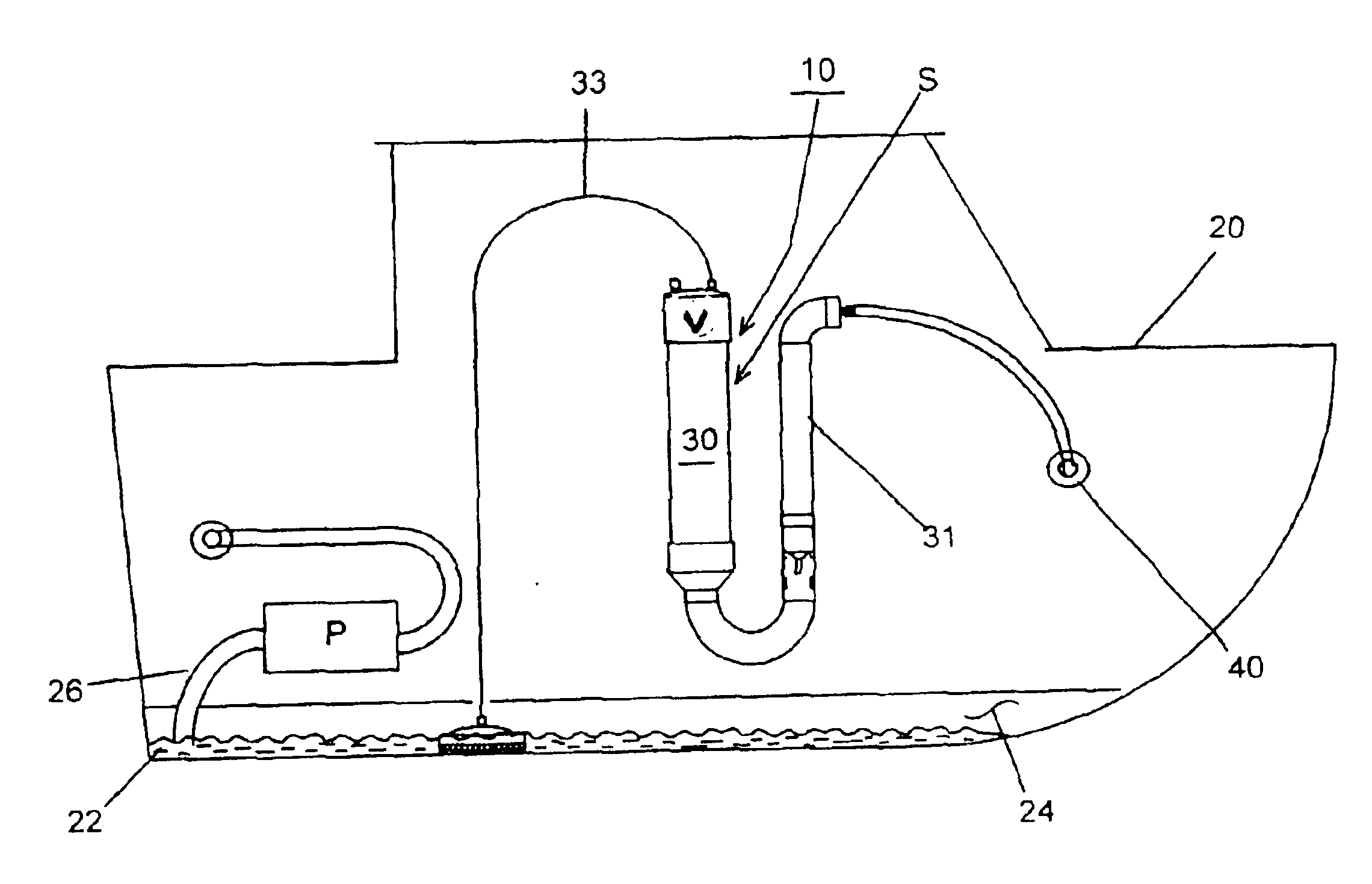
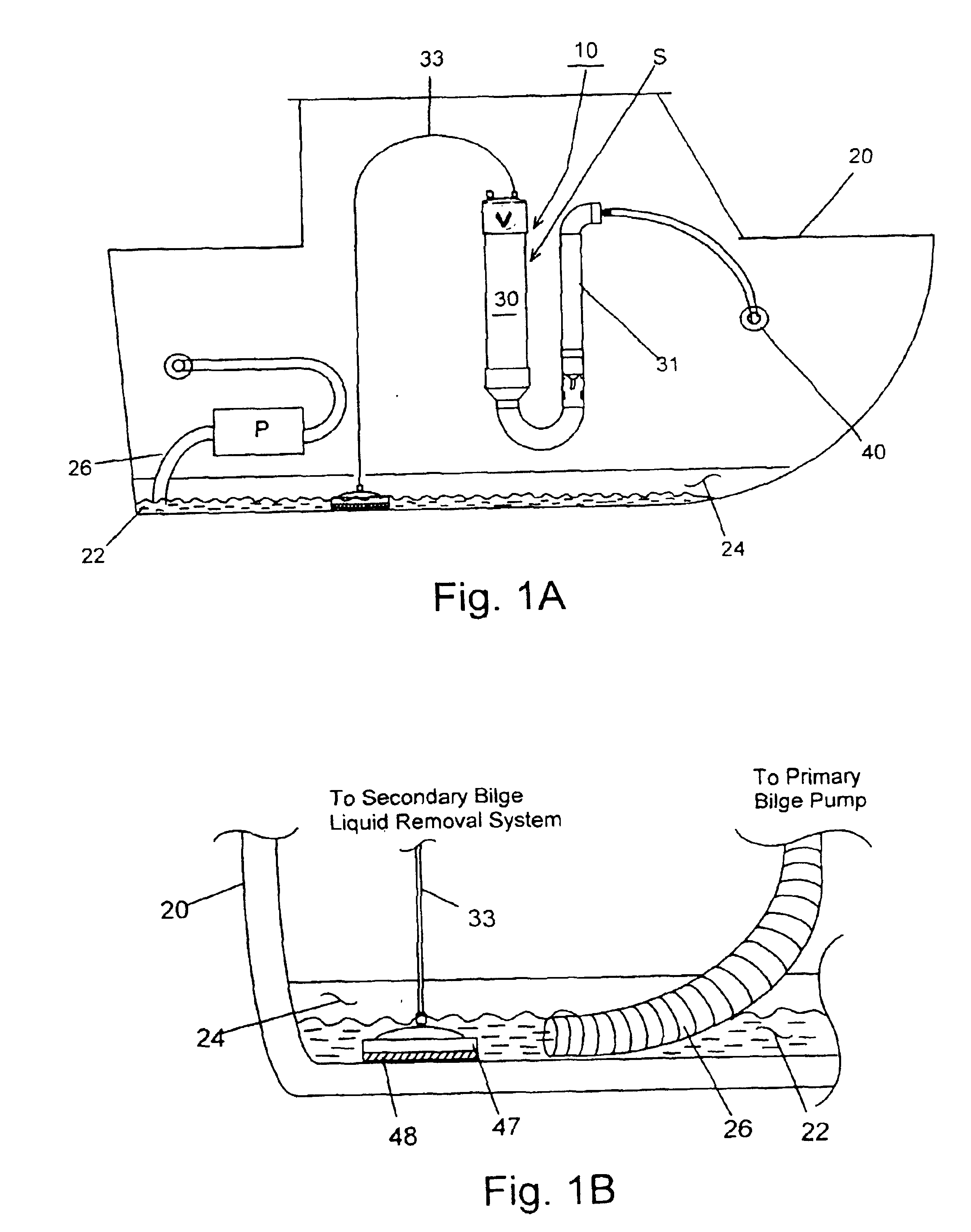
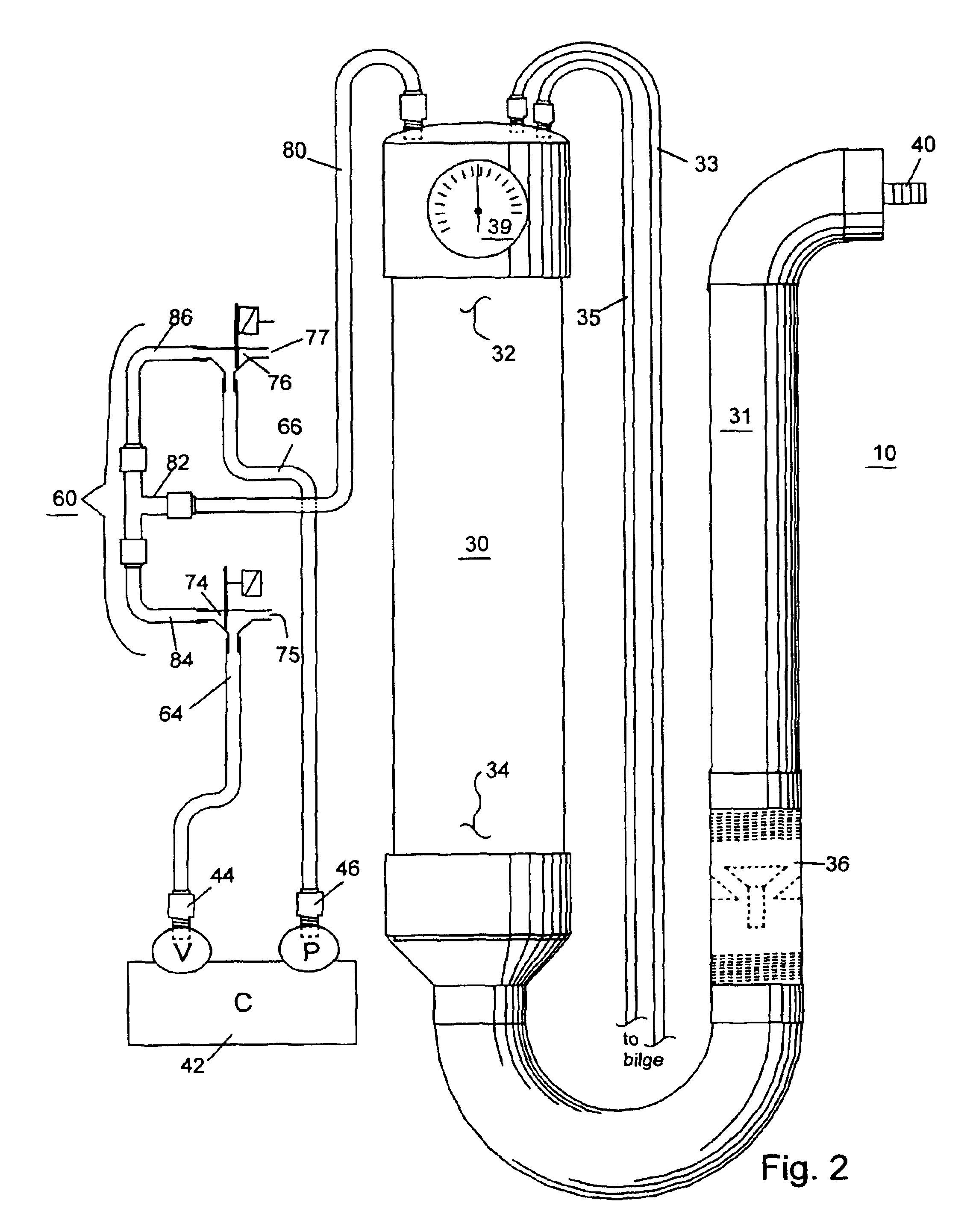
The present invention relates to a pneumatic bilge liquid removal system and method therefor. The pneumatic bilge liquid removal system 10 is diagrammatically illustrated in FIG. 1A on vessel 20. The pneumatic bilge liquid removal system 10 is typically used aboard a vessel, but is capable of operating from a location outside the vessel with collection hoses extending into the bilge area 24 of the vessel. In the preferred embodiment of the bilge liquid removal system 10 of the present invention, the system 10 operates as a secondary system (shown as “S” in FIG. 1A) in cooperation with a primary bilge system P. Accordingly, the primary bilge system P may be any type of bilge pump, as described in the background, capable of removing a large volume of bilge liquid or water 22 from the bilge area 24. The present invention is then utilized as a secondary bilge liquid removal system to remove the residual bilge liquid remaining after the primary system has cycled off. Of course, the prese...


PUM


Abstract

The invention relates to a pneumatic bilge liquid removal system including an air compressor having inlet and outlet ports pneumatically coupled to a valve system, a collection chamber with the top segment coupled to the valve system, at least one collection tube extending from the bilge to the collection chamber, a discharge tube coupled to the collection chamber, and a control system for the air compressor and valve system. The air compressor pressurizes the collection chamber via the outlet port for a first time interval causing the bilge liquid in the collection chamber to discharge through the discharge tube, and the air compressor creates a negative pressure in the collection chamber via the inlet port for a second time interval causing any the bilge liquid in the bilge to be drawn into and accumulate in the collection chamber via the collection tubes. A bilge liquid removal method is also provided.

Description

The present invention relates to a pneumatic bilge liquid removal system for removal of bilge liquids from vessels and a method therefor.BACKGROUND OF THE INVENTIONMankind has been devising methods and creating devices to remove liquids from a vessel's bilge since the building of the first boat. During the age of exploration, the reliable bucket was replaced with a simple tube with a piston sealed with leather. The piston was raised and lowered causing the bilge liquid to be expelled. In modern times, electrical / mechanical bilge pumps have been utilized.Today, automatic bilge pumps come in three basic forms: the centrifugal impeller, rubber lobe impeller and a diaphragm pump. All these designs share a common shortcoming. After the pump has cycled off or turned off, a base liquid level remains in the vessel's bilge. The present invention solves the problem of removing the base bilge liquid that remains after the primary bilge pumps have turned off.The vertical shaft impeller, submers...

Claims


Application Information

Patent Timeline
IPC IPC(8): F04F1/00F04F1/02
CPCF04F1/02
Inventor BAURLEY, ALFRED RUDOLPH
Owner BAURLEY ALFRED RUDOLPH
Why Eureka
Try Eureka