
Flow control valve

a flow control valve and valve body technology, applied in the direction of valve operating means/release devices, machines/engines, mechanical equipment, etc., can solve the problems of deterioration in the mountability increase in the manufacturing cost of the flow control valve, and increase in the cost of manufacturing the cooling system. , to achieve the effect of reducing the driving torque and downsizing the actuator

Inactive Publication Date: 2005-01-04
AISAN IND CO LTD +1
View PDF13 Cites 22 Cited by
  • Summary
  • Abstract
  • Description
  • Claims
  • Application Information

AI Technical Summary

Benefits of technology

The present invention has been made in view of the above circumstances and has a first object to overcome the above problems and to provide a flow control valve capable of preventing the thrust which acts on the valve due to a difference between a radiator flow pressure and a bypass flow pressure to relatively reduce the driving torque which an actuator is requested to produce, thereby achieving downsizing of an actuator.
In addition to the first object, a second object of the present invention is providing a flow control valve which can simply, inexpensively be mounted in an engine.

Problems solved by technology

This leads to a need to upsize the actuator, which may cause problems of a deterioration in mountability of the flow control valve with respect to the engine and an increase in manufacturing cost of the flow control valve.
Consequently, the cost of manufacturing the cooling system would be increased extremely.

Method used


Image

  • Flow control valve
  • Flow control valve
  • Flow control valve

Examples


first embodiment

[First Embodiment]

A detailed description of a first preferred embodiment of a flow control valve embodying the present invention will now be given referring to the accompanying drawings.

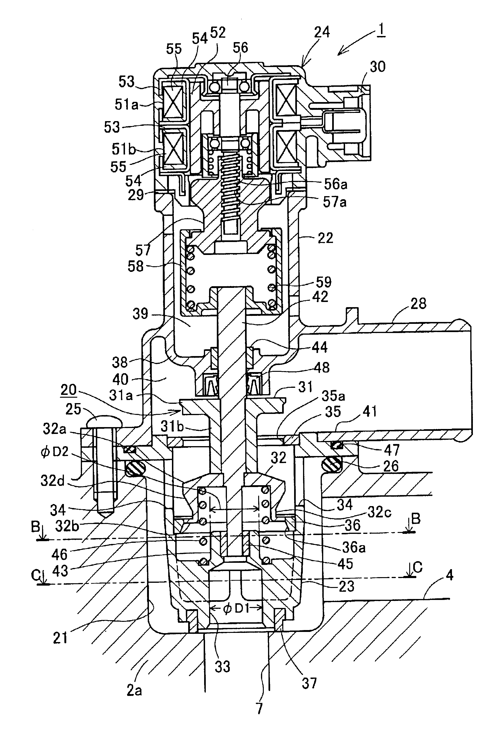
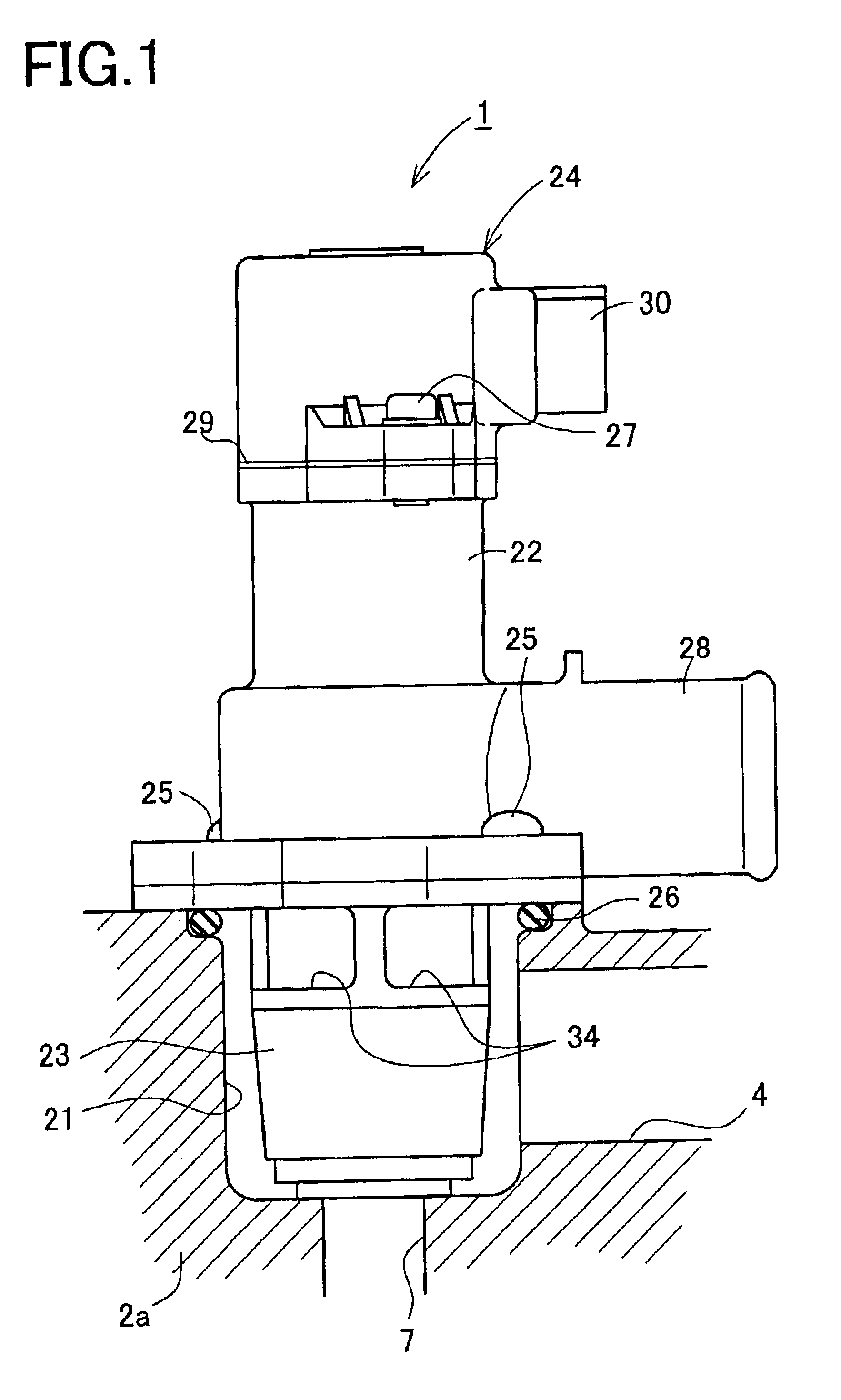
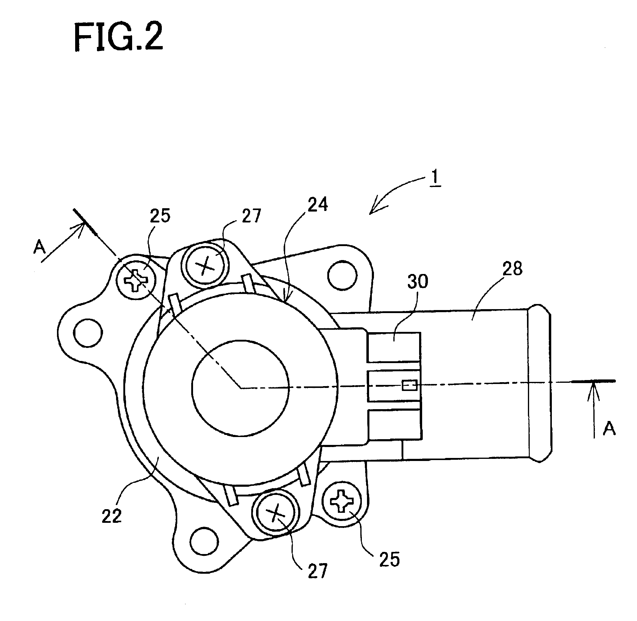
FIG. 1 is a side view of the flow control valve in the first embodiment. FIG. 2 is a plane view of the valve in FIG. 1. FIG. 3 is a longitudinal sectional view of the valve taken along a line A—A in FIG. 2. FIG. 4 is a cross sectional view of the valve taken along a line B—B in FIG. 3. FIG. 5 is a cross sectional view of the valve taken along a line C—C in FIG. 3. Arrows in FIG. 5 indicate the flow of water.

The flow control valve 1, which is integrated in a cooling system of a water-cooled engine used for automobiles, is used to control a flow quantity of cooling water. FIG. 6 is a schematic structural view of the cooling system. In FIG. 6, an engine 2 is internally provided with a cooling water passage 3 including a water jacket and others. An outlet port of the flow control valve 1 is connected to ...

second embodiment

[Second Embodiment]

Next, a second embodiment of a flow control valve embodying the present invention will be described with reference to the accompanying drawings. It is to be noted that like elements corresponding to those in the first embodiment are indicated by like numerals, and their explanations are omitted. This second embodiment is explained with a focus on different structures from those in the first embodiment.

FIG. 11 is a longitudinal sectional view of a flow control valve 61 in the present embodiment. FIG. 11 is based on FIG. 3. This flow control valve 61 includes a first valve body 71 and a first valve seat 72 which differ from those of the flow control valve 1 in the first embodiment.

The first valve body 71 has a substantially short cylindrical shape including a flange-shaped measuring part 71a formed in the upper portion. The first valve body 71 does not include the maximum flow quantity limiting part 31b provided in the first valve body 31 in the first embodiment. In...


PUM


Abstract

A flow control valve used in a cooling system of a water cooling type includes a first valve body and a first valve seat for controlling a quantity of radiator flow which returns from an engine to a pump through a radiator, a second valve body and a second valve seat for controlling a quantity of bypass flow which returns from the engine to the pump without passing through the radiator, and a step motor for displacing the valve bodies integrally as a valve unit. The first valve body, the first valve seat, the second valve body, and the second valve seat are so arranged that, in a range where the radiator flow quantity becomes practically zero, the bypass flow is permitted to flow at a slightly larger quantity than the radiator flow and, in other ranges, the bypass flow quantity is equal to or lower than the radiator flow quantity.

Description

BACKGROUND OF THE INVENTION1. Field of the InventionThe present invention relates to a flow control valve which is provided in a cooling system for cooling an engine by circulating cooling water through the engine and which is used for controlling a flow quantity of the cooling water.2. Description of Related ArtCooling systems of a water cooling type conventionally used in engines have generally been arranged to control cooling water at a constant temperature of about 80° C. by means of a thermostat without reference to an operating state of the target engine. However, changing a cooling degree of an engine according to an operating state (a loaded condition, a rotational speed, etc.) of the engine was found to be effective in reducing friction of the engine, improving fuel efficiency, enhancing knocking performance, and preventing the overheating of the cooling water. Accordingly, there have been proposed several types of cooling systems using cooling water each arranged to contro...

Claims


Application Information

Patent Timeline
Patent Type & Authority Patents(United States)
IPC IPC(8): F01P7/16F01P7/14F02F7/00F16K11/044F16K31/04
CPCF01P7/167F01P2007/146F01P2025/64F01P2025/52F01P2025/62F01P2025/32
Inventor KOBAYASHI, MASAHIROITO, HIROHISAYAMAMOTO, DAISUKEYOSHIKAWA, SHIGETAKASHINPO, YOSHIKAZUTAKAGI, ISAO
Owner AISAN IND CO LTD
Learn More