Fixation member and fixation apparatus having the fixation member

a fixation member and fixing device technology, applied in the field of image fixation members, can solve the problems of easy squeezing out of lubricant, easy slipping of lubricant, and easy increase of driving torque, so as to reduce driving torque, prevent stick slippage, and enhance wear resistance and sliding property between the inner peripheral surface of the fixation member and the pressure member.

Inactive Publication Date: 2014-03-27
SYNZTEC +2
View PDF4 Cites 3 Cited by
  • Summary
  • Abstract
  • Description
  • Claims
  • Application Information

AI Technical Summary

Benefits of technology

[0011]In view of the foregoing, an object of the present invention is to provide a fixation member which exhibits enhanced wear resistance and sliding property between the inner peripheral surface of the fixation member and a pressure member provided inside the fixation member, which can reduce driving torque at a fixation unit, and which does not cause stick slipping even in a high-load operational mode. Another object is to provide a fixation apparatus having the fixation member.
[0013]According to the first mode of the invention, the wear resistance and the sliding property between the inner peripheral surface of the fixation member and the pressure member can be enhanced. Thus, even when the fixation apparatus is operated in a high-load operational mode, the sliding property between the inner peripheral surface of the fixation member and the pressure member can be maintained. Therefore, the fixation member of the first mode can reduce the driving torque at a fixation unit and prevents stick slipping.
[0015]When a polyamide-imide resin is used, the wear resistance and the sliding property between the inner peripheral surface of the fixation member and the pressure member can be further enhanced. Thus, even when the fixation apparatus is operated in a high-load operational mode, the fixation member can reduce the driving torque at a fixation unit and ensures prevention of stick slipping.
[0017]When polytetrafluoroethylene is used, the wear resistance and the sliding property between the inner peripheral surface of the fixation member and the pressure member can be further enhanced. Thus, even when the fixation apparatus is operated in a high-load operational mode, the fixation member can reduce the driving torque at a fixation unit and ensures prevention of stick slipping.
[0019]According to the second mode of the present invention, the wear resistance and the sliding property between the inner peripheral surface of the fixation member and the pressure member can be enhanced. Thus, even when the fixation apparatus is operated in a high-load operational mode, the sliding property between the inner peripheral surface of the fixation member and the pressure member can be maintained. Therefore, the fixation apparatus of the present invention can reduce the driving torque at a fixation unit and prevents stick slipping.
[0020]According to the fixation member and the fixation apparatus having the fixation member of the present invention, the wear resistance and the sliding property between the inner peripheral surface of the fixation member and the pressure member provided inside the fixation member can be enhanced. Thus, even when the fixation apparatus is operated in a high-load operational mode such as a high-temperature, low-speed operational mode, the sliding property between the inner peripheral surface of the fixation member and the pressure member can be maintained. Therefore, the fixation member and the fixation apparatus of the present invention can reduce the driving torque at a fixation unit and prevents stick slipping.

Problems solved by technology

However, even when such a lubricant is present, the sliding property between the inner peripheral surface of the fixation member and the pressure member decreases during a long-term operation or a high-load operation, to thereby problematically increase driving torque.
However, even when such a slide layer is provided, in the case where the fixation apparatus is operated for a long time, particularly in a high-temperature, low-speed operational mode (e.g., in image fixation on a thick print medium such as an OHP sheet), the lubricant intervening between the inner peripheral surface of the fixation member and the pressure member is exposed to high temperature, so that the viscosity of the lubricant lowers, whereby squeezing out of the lubricant easily occurs.
Once the lubricant is squeezed out, lubrication between the inner peripheral surface of the fixation member and the pressure member becomes poor, and stick slipping occurs.
In this case, the slide layer problematically wears.

Method used


Image

  • Fixation member and fixation apparatus having the fixation member
  • Fixation member and fixation apparatus having the fixation member
  • Fixation member and fixation apparatus having the fixation member

Examples


embodiment 1

[0029]The fixation member according to the present invention is suitably employed in a fixation unit of an image-forming apparatus so as to fix an unfixed toner image onto a recording medium through heat and pressure at the fixation unit. In Embodiment 1, the fixation member is an endless fixation belt (an endless belt or an endless film).

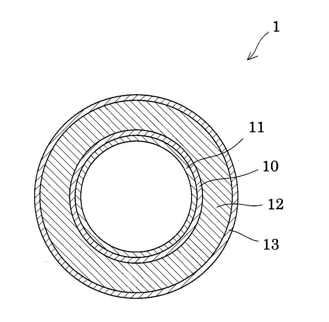
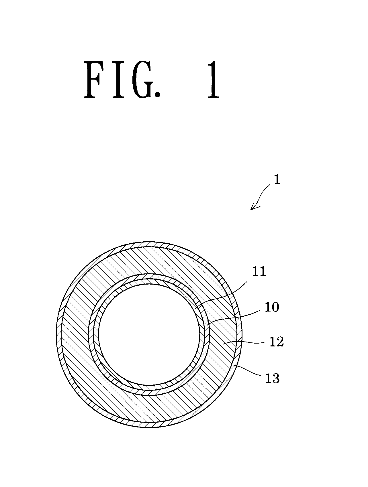
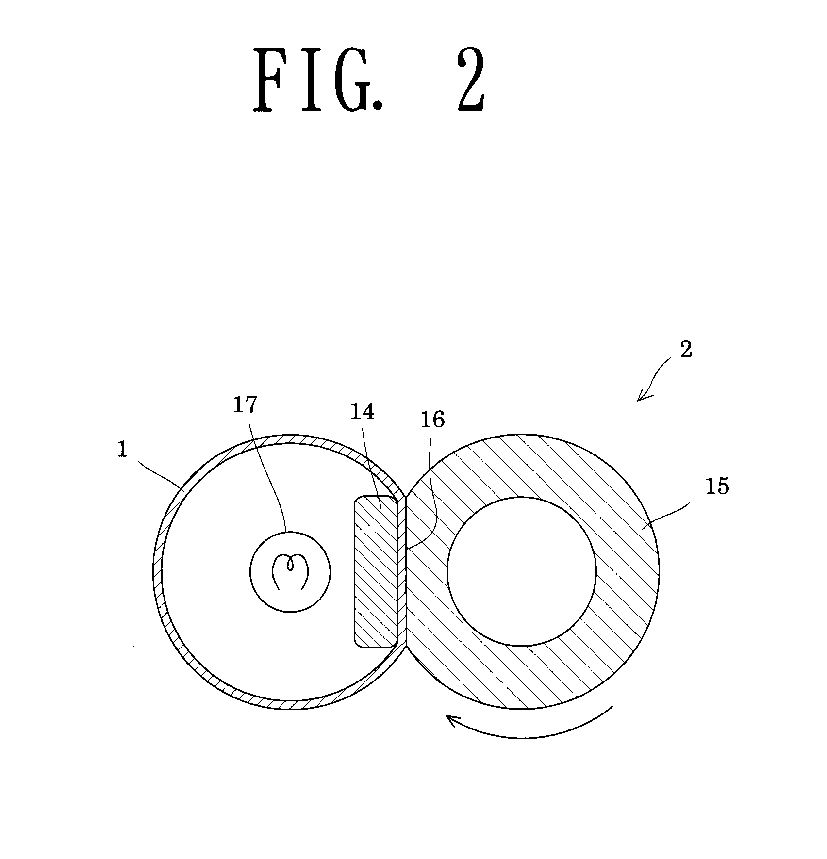
[0030]FIG. 1 is a schematic cross-section of a fixation belt 1. The fixation belt 1 has a metallic substrate 10 having at least one layer of an electrocast seamless belt, a slide layer 11 formed on the inner peripheral surface of the metallic substrate 10, an elastic layer 12 formed on the outer peripheral surface of the metallic substrate 10, and a release layer 13 formed on the outer peripheral surface of the elastic layer 12. That is, the slide layer 11, the metallic substrate 10, the elastic layer 12, and the release layer 13 are sequentially stacked from the inside.

[0031]The metallic substrate 10 has at least one layer of a nickel or nickel al...

embodiment 2

[0064]Embodiment 2 is a variation of the fixation apparatus. The same members as employed in Embodiment 1 are denoted by the same reference numerals, and overlapping descriptions will be omitted. FIG. 3 is a schematic cross-section of a fixation apparatus according to Embodiment 2.

[0065]As shown in FIG. 3, a fixation apparatus 2A has a fixation belt 1, a pressure roller 15 disposed so as to face opposite the fixation belt 1, and, instead of the pressure member 14, a fixation roller 18 that outwardly presses the fixation belt 1 against the pressure roller 15. A heating means for heating the fixation belt 1 may be disposed inside the fixation roller 18 or outside the fixation belt 1.

embodiment 3

[0066]Embodiment 3 is a variation of the fixation apparatus. The same members as employed in Embodiment 1 are denoted by the same reference numerals, and overlapping descriptions will be omitted. FIG. 4 is a schematic cross-section of a fixation apparatus according to Embodiment 3.

[0067]As shown in FIG. 4, a fixation apparatus 2B has a fixation belt 1, a pressure roller 15 disposed so as to face opposite the fixation belt 1, an inner roller 19 that outwardly presses the fixation belt 1 against the pressure roller 15, and a heating roller 20 inside which heating means 17 is disposed. In the fixation belt 1, the inner roller 19 and the heating roller 20 including the heating means 17 therein are disposed, whereby the fixation belt 1 is rotated by means of the inner roller 19 and the heating roller 20. In Embodiment 3, the heating means 17 for the heating roller 20 may be disposed outside the fixation belt 1.


PUM


Abstract

The present invention provides a fixation member which exhibits enhanced wear resistance and sliding property between the peripheral surface of the fixation member and a pressure member, which can reduce driving torque at a fixation unit, and which does not cause stick slipping even in a high-load operational mode, and a fixation apparatus having the fixation member. The fixation member employed in a fixation unit of the fixation apparatus has a metallic substrate having at least one layer of an electrocast seamless belt, and a slide layer disposed on the inner peripheral surface of the metallic substrate, wherein the slide layer is formed of at least one species of the group consisting of a polyamide-imide resin and a polyimide resin, and a fluororesin; the slide layer has a fluororesin content of 27.5 mass % to 50 mass %; and the slide layer has a surface roughness Ra of 0.4 μm or less.

Description

[0001]The entire disclosure of Japanese Patent Applications No. 2012-207949 filed on Sep. 21, 2012 and No. 2013-163439 filed on Aug. 6, 2013 is expressly incorporated by reference herein.BACKGROUND OF THE INVENTION[0002]1. Field of the Invention[0003]The present invention relates to an image-fixation member (hereinafter referred to simply as a “fixation member”) and an image-fixation apparatus (hereinafter referred to simply as a “fixation apparatus”) having the fixation member. More particularly, the invention relates to a fixation member and a fixation apparatus suitable for use in a fixing unit of an image-forming apparatus such as a copying machine, a facsimile machine, or a laser beam printer.[0004]2. Background Art[0005]A type of a fixation apparatus employed in an image-forming apparatus has an endless fixation belt (fixation member), a pressure roller disposed so as to face opposite the fixation member, and a pressure member that outwardly presses the fixation member against...

Claims


Application Information

Patent Timeline
Patent Type & Authority Applications(United States)
IPC IPC(8): G03G15/20
CPCG03G15/2057G03G2215/2035
Inventor SUGIYAMA, SHINGOSUZUKI, MASAYANISHIDA, AKIRAOKABE, HITOSHIKITAHARA, TETSUHIROYAMASAKI, YUJIRO
Owner SYNZTEC
Why Eureka
Try Eureka