
Apparatus for mounting a brake drum to a bicycle frame

a technology for brake drums and bicycle frames, which is applied to bicycle brakes, braking components, cycle equipments, etc., can solve the problems of hub brake devices twirling and making noise when the brake is applied, and gaps may exist between the lock section and the locking spa

Inactive Publication Date: 2005-01-04
SHIMANO INC
View PDF12 Cites 13 Cited by
  • Summary
  • Abstract
  • Description
  • Claims
  • Application Information

AI Technical Summary

Problems solved by technology

This is very inconvenient, especially when a quick-release hub that permits easy replacement of the wheel is used.
In the conventional mounting construction described above, a gap may exist between the lock section and the locking space when the lock section is disposed in the locking space due to erroneous mounting of the bracket securing member or the like.
If a gap exists in the hub axial direction or the rotational direction, there is a danger that the hub brake device will rattle and make noise when the brake is applied.

Method used


Image

  • Apparatus for mounting a brake drum to a bicycle frame
  • Apparatus for mounting a brake drum to a bicycle frame
  • Apparatus for mounting a brake drum to a bicycle frame

Examples


Embodiment Construction

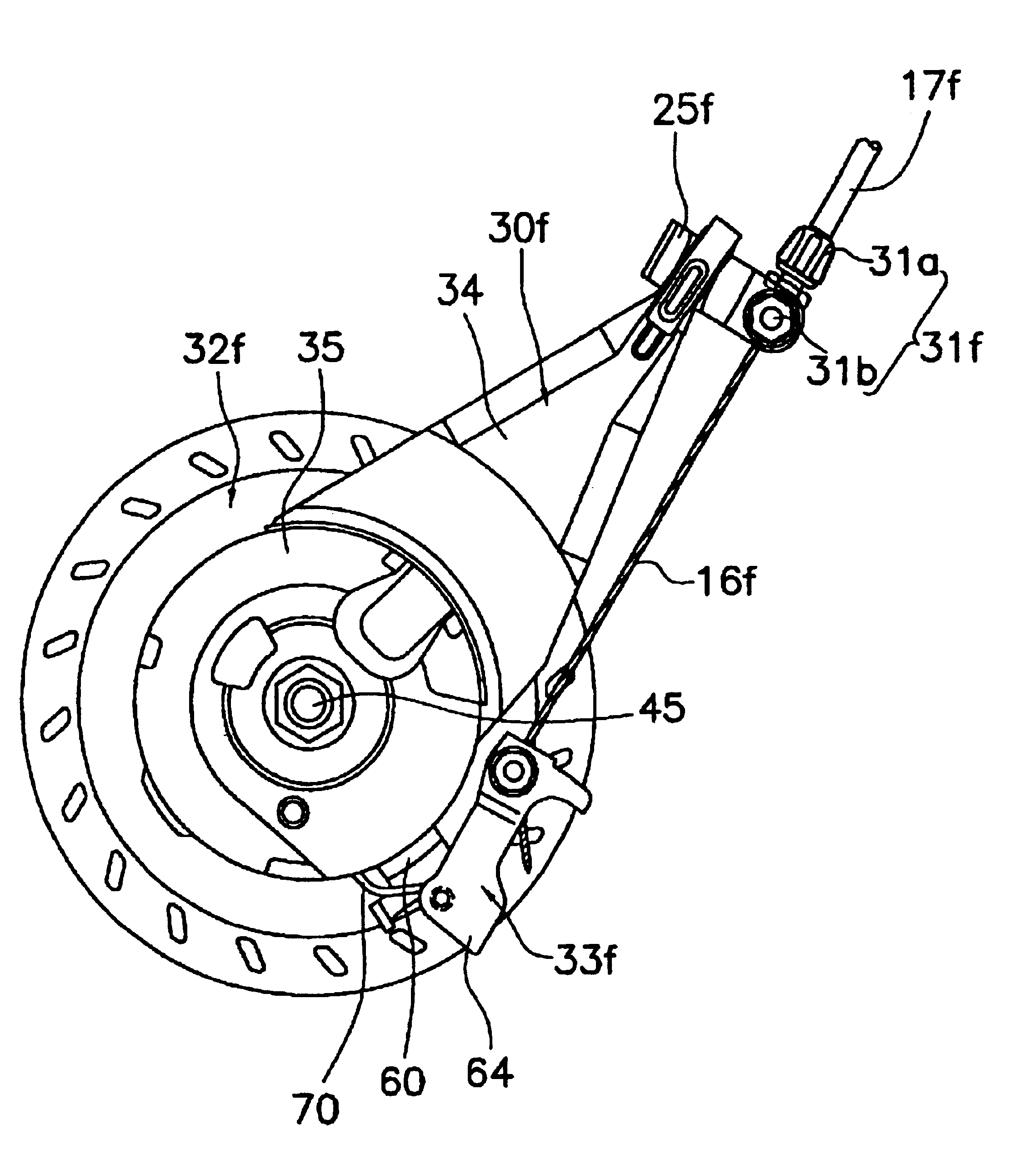
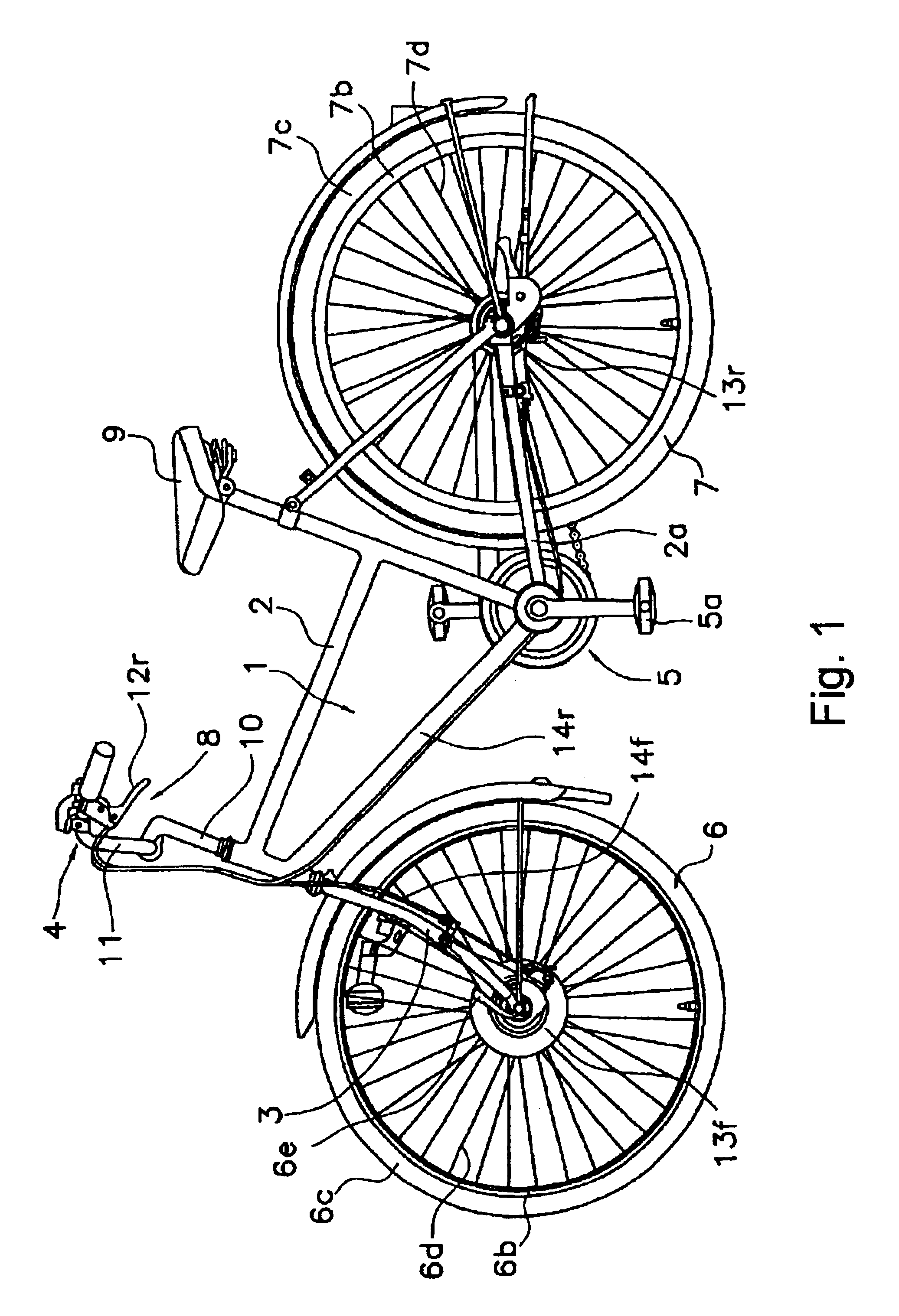
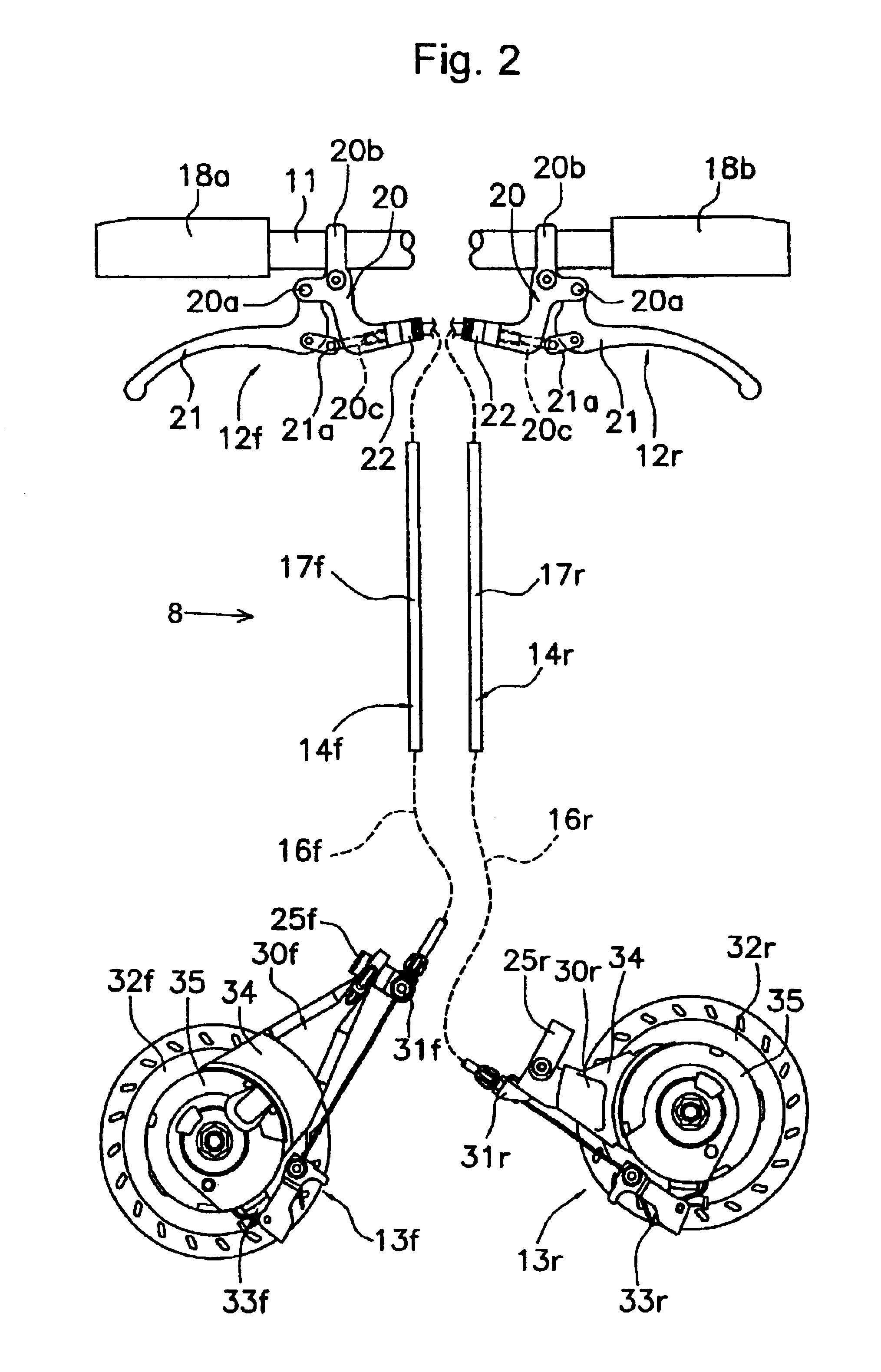
FIG. 1 is a side view of a particular embodiment of a bicycle that includes braking components described herein. In this embodiment, the bicycle comprises a frame 1 that has a frame body 2 and a front fork 3; a handlebar portion 4 comprising a handle stem 10 fastened to the top of front fork 3 and a handlebar 11 fastened to handle stem 10 for steering; a saddle 9 for sitting; a front wheel 6; a rear wheel 7; a brake system 8 for braking front wheel 6 and rear wheel 7; and a drive section 5 for transmitting rotation of pedals 5a to rear wheel 7.

Front wheel 6 and rear wheel 7 have front and rear hubs 6a (FIG. 4, wherein only the front hub 6a is shown), each having a hub spindle 15a (FIG. 6), front and rear rims 6b, 7b (FIG. 1) disposed at the outside periphery of hubs 6b, tires 6c, 7c attached to front and rear rims 6b, 7b, and spokes 6d, 7d connecting the hubs 6a with the respective rims 6b, 7b. As shown in FIG. 6, hub 6a hub spindle 15a is nonrotatably mounted on front fork 3 of fra...


PUM


Abstract

A apparatus is provided for mounting a brake device to a bicycle frame, wherein the brake device brakes the hub of a wheel that rotates around a hub shaft. The apparatus comprises a fastening bracket, a bracket fastening member, and an insert member. The fastening bracket comprises a base portion adapted to receive the hub shaft therethrough; an arm portion that extends outwardly from the base portion; and a detaining portion having first and second side surfaces disposed on the arm portion for mounting the brake device to the bicycle frame. The bracket fastening member has a detaining space into which the detaining portion is inserted for detaining the fastening bracket to the bicycle frame, and the insert member has first and second contact portions that face the respective first and second side surfaces of the detaining portion when the insert member is disposed in the detaining space.

Description

BACKGROUND OF INVENTIONThe present invention is directed to bicycle brake devices and, more particularly, to bicycle brake devices that are used to brake a hub of a bicycle wheel.Bicycle braking devices currently available include rim braking devices and hub braking devices. Rim braking devices include cantilever brakes or caliper brakes that brake the rim of the wheel. Hub braking devices brake the wheel hub, and they include drum brakes, band brakes, roller brakes and the like. A hub brake brakes the hub of the wheel, so it is able to provide braking even if the wheel rim is warped.Conventional bicycle hub brake devices comprise a fastening bracket nonrotatably mounted to the bicycle frame, a brake drum that rotates integrally with the hub, a brake member such as a brake shoe or a brake band that provide a braking action on the brake drum, and a brake operating component for bringing the brake shoes into pressed contact with the braking surface of the brake drum.The fastening brac...

Claims


Application Information

Patent Timeline
Patent Type & Authority Patents(United States)
IPC IPC(8): B62L1/00B62K19/38F16D51/12F16D65/02
CPCB62L1/005B62L1/00
Inventor MATSUEDA, KEIJI
Owner SHIMANO INC
Learn More