
Modular plastic conveyor belt with high beam strength

a conveyor belt and module technology, applied in the direction of conveyors, packaging, transportation and packaging, etc., can solve the problems of black specks or worn-off metal bits falling on the conveyed articles, not being able to accept black specks, and not having a lot of beam strength

Active Publication Date: 2005-01-04
LAITRAM LLC
View PDF26 Cites 53 Cited by
  • Summary
  • Abstract
  • Description
  • Claims
  • Application Information

AI Technical Summary

Benefits of technology

Although the invention has been described in detail with reference to some preferred versions, other versions are possible. For example, a straight-running belt could be built with the indexing and beam strength as described. Consequently, the scope of the claims are not limited to the preferred versions described in detail.

Problems solved by technology

But, as metal belts wear, black specks or worn-off bits of metal fall on the conveyed articles.
In many food applications, black specks are not acceptable.
Plastic belts with a lot of open area for air flow and for the collapsibility required to negotiate turns, however, do not normally have much beam strength.
This lack of beam strength causes conventional plastic conveyor belts to sag between the spaced apart supports.
In a tightly stacked spiral system, the belt sag can interfere with supporting conveyor structure.

Method used


Image

  • Modular plastic conveyor belt with high beam strength
  • Modular plastic conveyor belt with high beam strength
  • Modular plastic conveyor belt with high beam strength

Examples


Embodiment Construction

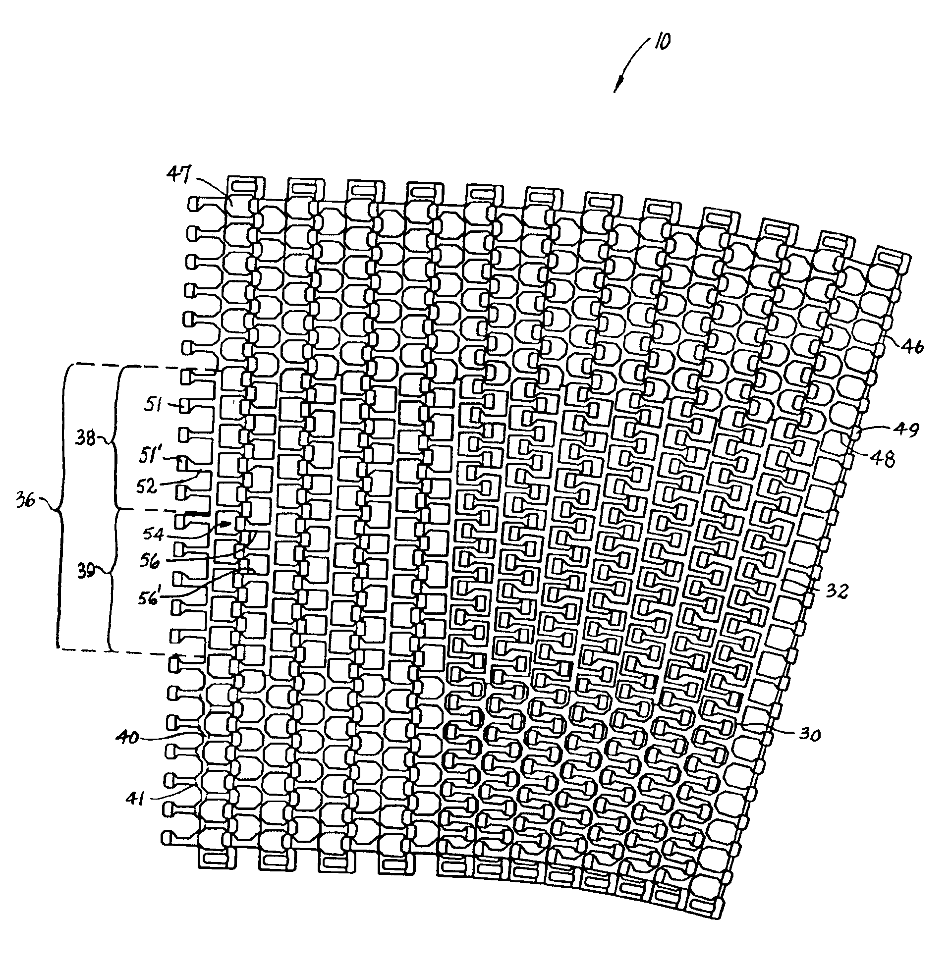
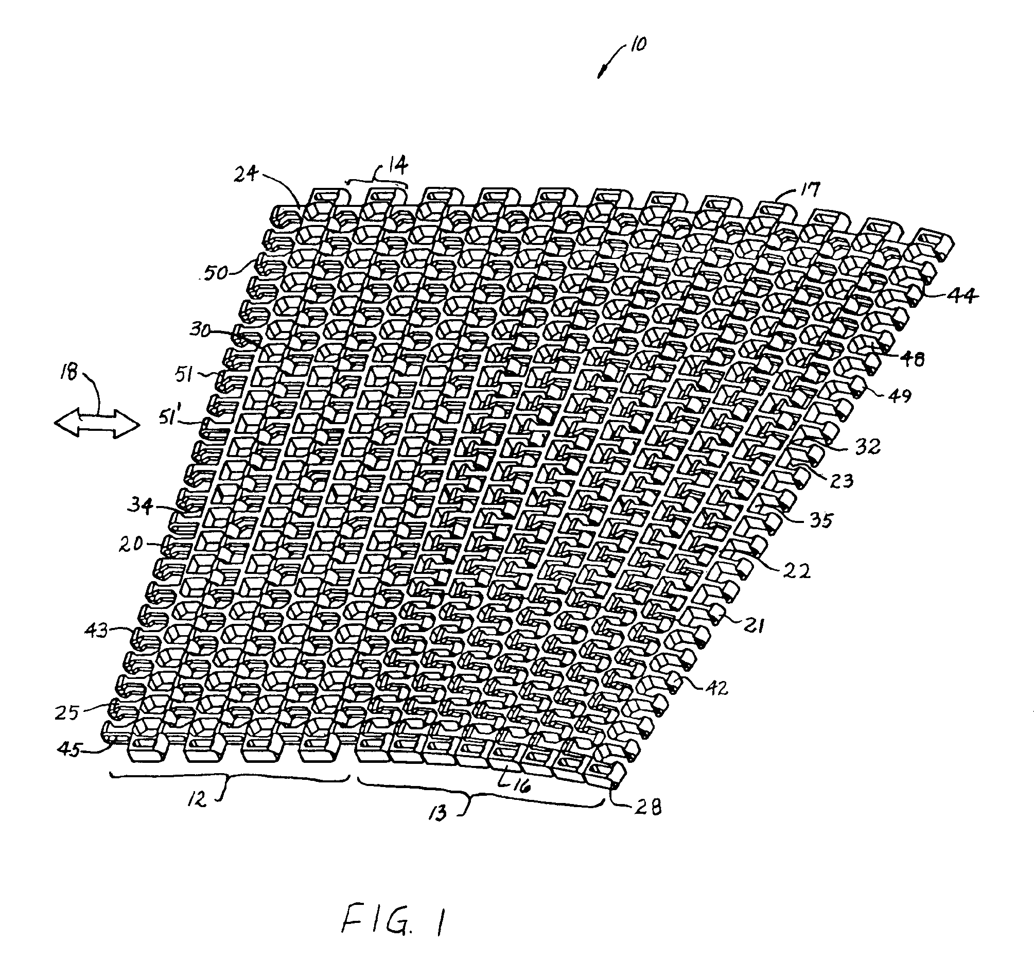
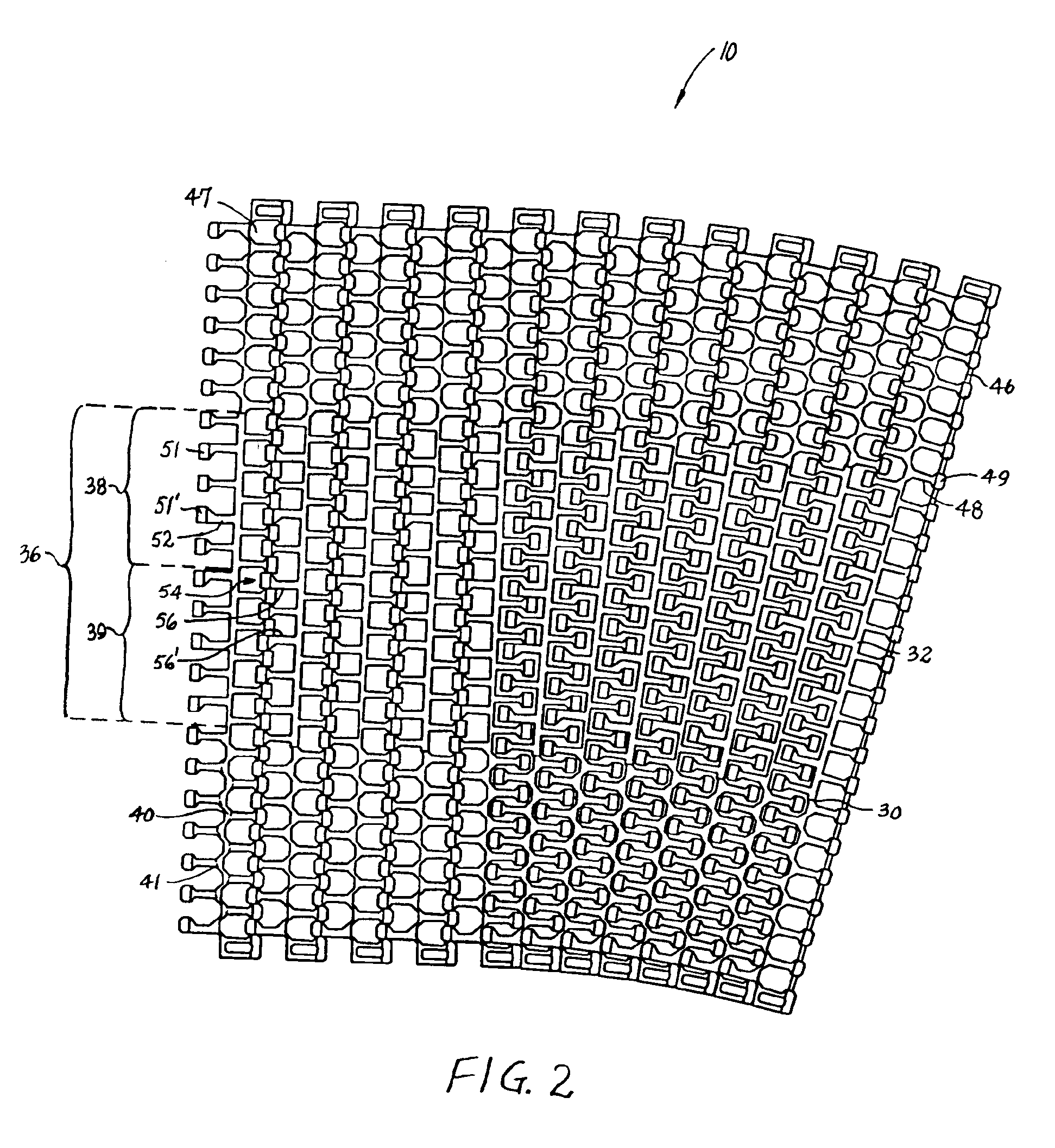
A portion of a modular plastic conveyor belt embodying features of the invention is shown in FIGS. 1 and 2. The conveyor belt 10 is shown in FIG. 1 following a conveying path that includes straight 12 and curved 13 segments. The belt consists of a series of rows 14 of belt modules. Each row extends laterally in width from a first side edge 16 to a second side edge 17 and in the direction of belt travel 18, which may be bi-directional, from a leading end 20 to a trailing end 21. The modules extend in depth from a top side 22, on which articles are conveyed, to a bottom side 23. (The descriptors “leading” and “trailing” and “top” and “bottom” are not meant to limit the belt to a certain direction of travel or a certain orientation, but merely to help describe the general spatial relationship of various components of the example versions described.) Each row is made up of a number of belt modules arranged side by side. In this example, a row includes a first side edge module 24 and a s...


PUM


Abstract

A modular plastic conveyor belt having a central beam along each belt row. The beam extends laterally across the width of a belt row and includes a linear portion in a middle region of the belt and a sinuous region near both side edges of the belt. In the linear region, the beam includes a portion of constant thickness with linearly tapering portions toward the side edges of the belt. In this way, the thicker portions of the beam in the middle of the belt provide beam strength to allow less frequent support beneath the belt and the thinner sinuous portions at the edges of the belt give it the flexibility and mobility to collapse at the inside of a turn.

Description

BACKGROUND OF INVENTIONThe invention relates generally to power-driven conveyors and, more particularly, to modular plastic conveyor belts suitable for following curved paths.Many conveying applications require conveyor belts to transport articles along curved paths. In low-tension spiral conveyors, for example, a conveyor belt is wrapped helically around a cylindrical drive tower in a compact arrangement for use inside a freezer or on a cooling line. Conventionally, metal conveyor belts have been used with spiral conveyors. But, as metal belts wear, black specks or worn-off bits of metal fall on the conveyed articles. In many food applications, black specks are not acceptable. In response to the black-speck problem and other food-contamination problems, modular plastic conveyor belts have begun replacing metal belts in food applications. In an ideal situation, a modular plastic belt is a drop-in replacement for a metal belt once the take-up, tensioning, and other sprockets are repl...

Claims


Application Information

Patent Timeline
Patent Type & Authority Patents(United States)
IPC IPC(8): B65G17/08B65G17/06
CPCB65G17/086B65G2207/30B65G2207/24B65G2201/02B65G21/18
Inventor KLEIN, RICHARD M.DUHON, LYNELL M.KNOTT, ERROL P.
Owner LAITRAM LLC
Learn More