Stackable open top containers

a technology of open top containers and sleeve, which is applied in the field of containers, can solve the problems of imposing a significant cost penalty, complicating the container inventory requirements, and complicated container construction, and achieves the effects of minimizing peripheral deformation, maximizing seating support, and enhancing the ability of the sleeve to resist distortion

Inactive Publication Date: 2005-01-04
SHUERT LYLE H
View PDF15 Cites 28 Cited by
  • Summary
  • Abstract
  • Description
  • Claims
  • Application Information

AI Technical Summary

Benefits of technology

According to the invention, the bottom of each leg includes an outboard upper level portion sized to seat a section of an upper edge of a lower tubular sleeve and an inboard lower level portion sized to fit within the upper edge of the lower sleeve. With this arrangement, with the upper sleeve positioned on the platform portion to form the container the pallet may be seated on the lower sleeve with the outboard upper level portions of the bottoms of the pallet legs seated on sections of the upper edge of the lower sleeve and the inboard lower level portions of the pallet bottoms positioned snugly within the upper edge of the lower sleeve to maintain the sleeves of successive containers in a stack in alignment.
According to a further feature of the invention, each sleeve comprises a composite sleeve assembly including inner and outer telescopically arranged sleeve members and each sleeve member comprises a multi-ply corrugated cardboard structure. This arrangement enhances the ability of the sleeve to resist distortion in a stacked environment.
According to a further feature of the invention, each leg is hollow and includes a bottom wall defining the bottom of the leg; the outboard upper level portion of each leg bottom comprises an outboard bottom wall upper level portion having upper and lower faces; the lower level portion of each leg bottom comprises an inboard bottom wall lower level portion; the lower edge of the upper sleeve is seated on the upper faces of the outboard bottom wall upper level portions; and the upper edge of the lower sleeve is seated on the lower faces of the outboard bottom wall upper level portions. This arrangement provides a ready and efficient means of seating the upper and lower sleeves in a stacked configuration while maintaining the sleeves of successive containers in a stack in alignment.
According to a further feature of the invention, the lower face of the pallet is configured to define tunnels between the pallet legs and the lower edge of the upstanding sleeve is selectively cut away to define the lower edge seat sections and to further define raised lower edge sections interconnecting the seat sections and spanning the tunnels of the pallet. This arrangement allows the downward compressive forces applied to stacked containers to be transferred by the sleeve substantially directly to the supporting surface thereby minimizing deformation of peripheral portions of the base pallet.
According to a further feature of the invention, the pallet includes corner legs; the upper and lower faces of the outboard upper level bottom wall portions of each corner leg have an L-shaped configuration; the lower edge of the upstanding sleeve is configured to define L-shaped corner seat sections conforming to the configuration of the upper face of the outboard upper level bottom wall portion of the corner leg; and the upper edge of the lower container sleeve is configured to define L-shaped corner portions conforming to the configuration of the lower face of the outboard upper level bottom wall portions of the comer legs. This arrangement maximizes the seating support for the upper and lower sleeves and firmly supports the upper edge of the lower sleeve throughout the entire periphery of the sleeve to maintain sleeve alignment in stacked containers.

Problems solved by technology

However, where a lid is not necessary to protect the contents the need for a lid to allow stacking of the containers complicates the container construction, complicates the container inventory requirements, and imposes a significant cost penalty.

Method used


Image

  • Stackable open top containers
  • Stackable open top containers
  • Stackable open top containers

Examples


Embodiment Construction

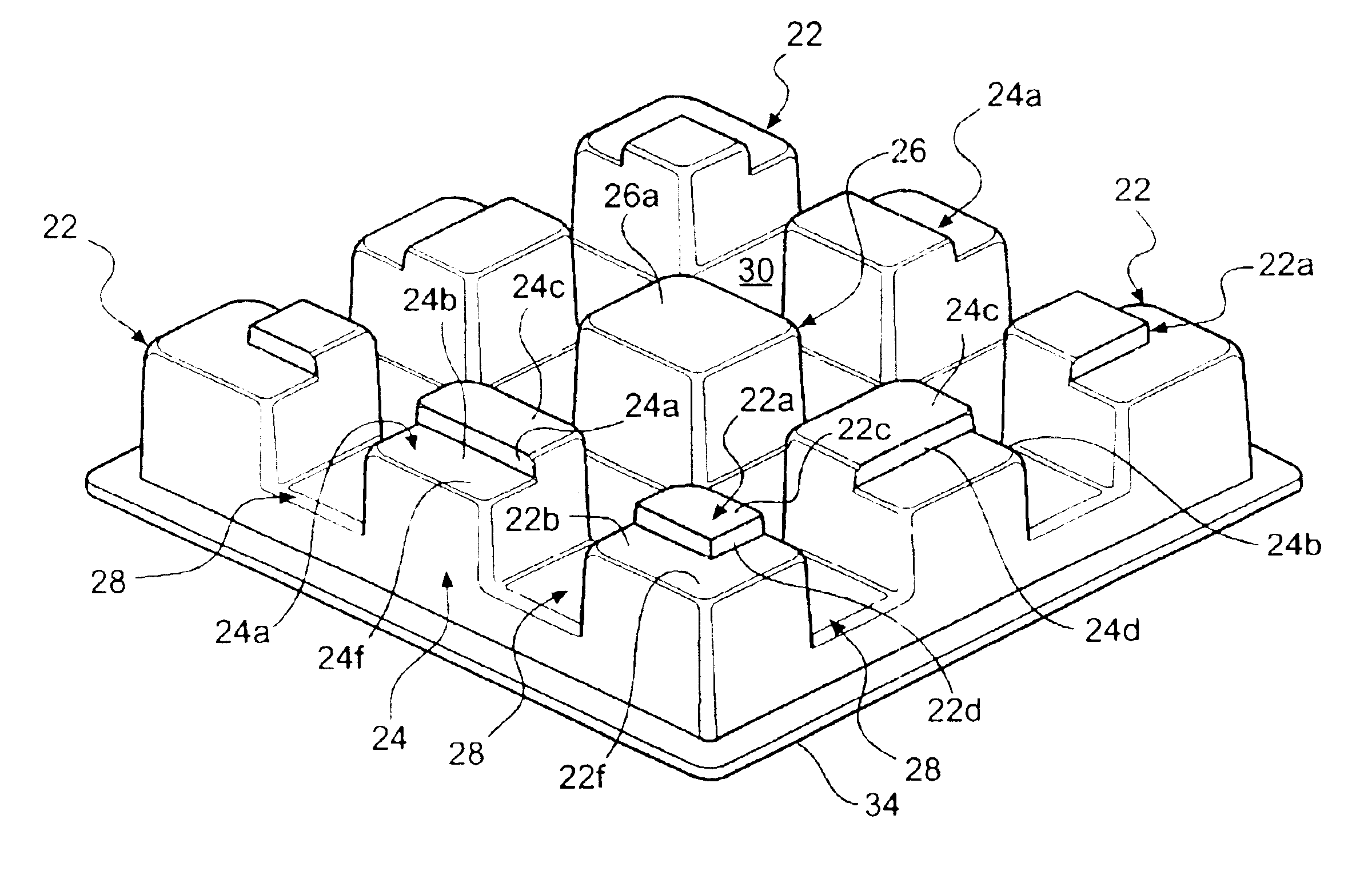
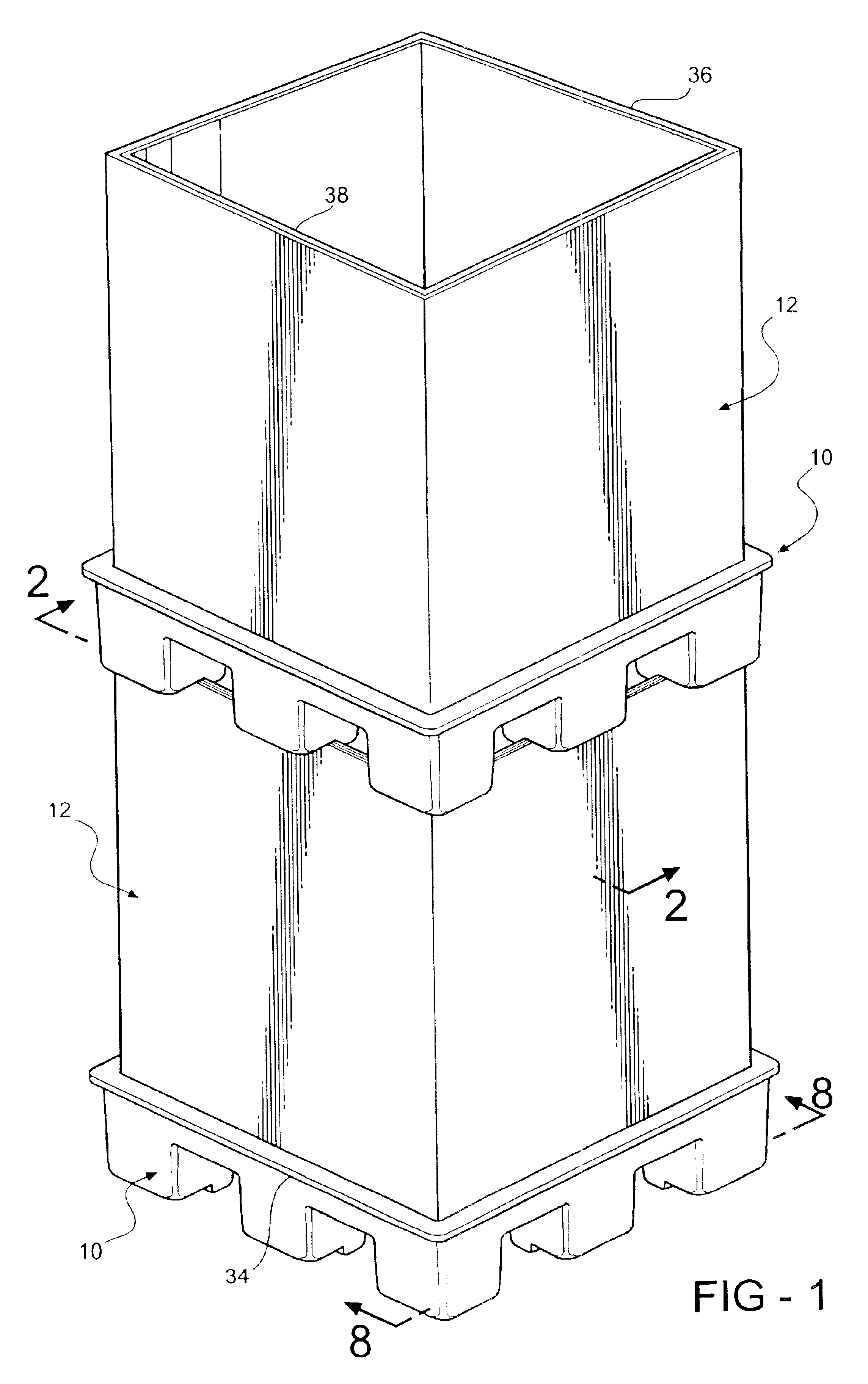
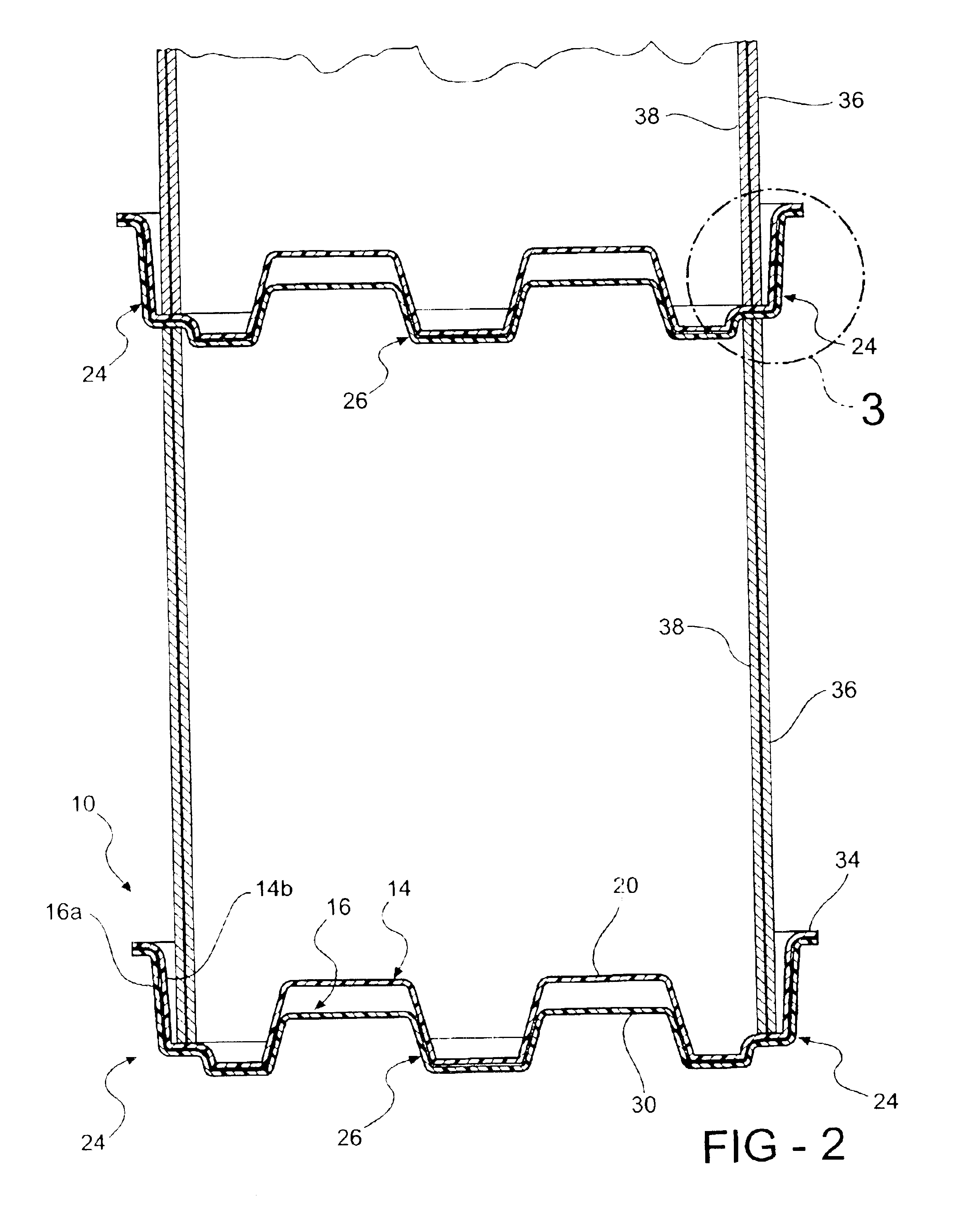
The container of the invention, broadly considered, includes a pallet 10 and a sleeve 12. Pallet 10 is formed of a rigid plastic material and preferably employs a twin sheet construction including two sheets 14 and 16 of organic polymeric material such as polyethylene which are vacuum formed and fused or knitted together at various points to add structural rigidity. Pallet 10 is generally planar and includes a planar platform structure 18 defining a flat upper load face 20 and a plurality of hollow legs extending downwardly from platform structure 18 and opening in upper face 20. As shown, corner legs 22 are provided at each corner of the pallet, intermediate legs 24 are provided at an intermediate location along each side of the pallet, and a central leg 26 is provided centrally of the pallet.

Legs 22, 24 and 26 will be seen to cooperate to define tunnels or indentations 28 extending transversely and longitudinally across the lower face 30 of the pallet to provide relieved access ar...


PUM


Abstract

A container including a rigid plastic pallet and a tubular sleeve positioned in upstanding fashion on the pallet to form the container. The pallet includes a platform portion adapted to receive a lower edge of the tubular sleeve and a plurality of peripherally spaced hollow legs downstanding from the platform portion and each including a bottom wall. The bottom wall of each leg has an outboard upper level portion and an inboard lower level portion. The upper level portion of each leg has an upper face sized to receive a seat section of the lower edge of the upstanding sleeve and a lower face sized to seat a section of an upper edge of the tubular sleeve of a lower container in a stack of containers. The inboard lower level portions are sized to fit within the upper edge of the lower container sleeve to maintain successive sleeves in a stack of containers in alignment and insure that compressive loading in the sleeves in transferred downwardly to the support surface for the stack. Each sleeve comprises a composite sleeve assembly including inner and outer telescopically arranged sleeve members and each sleeve member comprises a multi-ply corrugated cardboard structure.

Description

BACKGROUND OF THE INVENTIONThis invention relates to containers and more particularly to containers of the type including a rigid pallet and a tubular sleeve upstanding from the pallet.Pallet and sleeve containers are in common usage and may be used for storing either bulk material or discreet free standing articles. In either case it is often necessary or desirable to stack a plurality of loaded containers. The extreme weight imposed in the stack, particularly on lower containers in the stack, makes it necessary to insure that the sleeves, especially of the lower containers, are not damaged by the extreme compressive loading in the stack.One arrangement to prevent sleeve damage in a container stack has been to provide a rigid plastic lid to fit over the top edge of each sleeve in the stack so that the sleeves of successive containers in the stack remain in alignment and the compressive loading is transferred to the support surface for the stack. In scenarios where a lid is otherwis...

Claims


Application Information

Patent Timeline
Patent Type & Authority Patents(United States)
IPC IPC(8): B65D19/00B65D19/02B65D19/20
CPCB65D19/004B65D19/20B65D2519/00034B65D2519/00069B65D2519/00159B65D2519/00273B65D2519/00975B65D2519/00338B65D2519/00502B65D2519/00562B65D2519/00621B65D2519/00641B65D2519/00303
Inventor SHUERT, LYLE H.
Owner SHUERT LYLE H
Why Eureka
Try Eureka