Aircraft rotor and aircraft

a technology of aircraft rotor and rotor plate, which is applied in the direction of flying saucers, vertical landing/take-off aircraft, aircraft navigation control, etc., can solve the problem of complex control mechanics and achieve the effect of improving efficiency

Inactive Publication Date: 2005-01-04
NATURAL COLOR KARI KIRJAVAINEN
View PDF14 Cites 14 Cited by
  • Summary
  • Abstract
  • Description
  • Claims
  • Application Information

AI Technical Summary

Benefits of technology

The invention provides the advantage that the aircraft can be steered in a very versatile manner and relatively easily. The aircraft can change its direction of travel quickly and the direction of the body can be adjusted by adjusting the torque of the rotors. Steering the aircraft is possible without needing to bank it. By arranging the surface area of the upper part of the body to be larger than that of the lower part of the body makes it possible to utilize the ascending force of the body during level flight and to achieve a better efficiency than in helicopters, for instance.

Problems solved by technology

All in all, this type of control mechanics is quite complex.

Method used


Image

  • Aircraft rotor and aircraft
  • Aircraft rotor and aircraft
  • Aircraft rotor and aircraft

Examples


Embodiment Construction

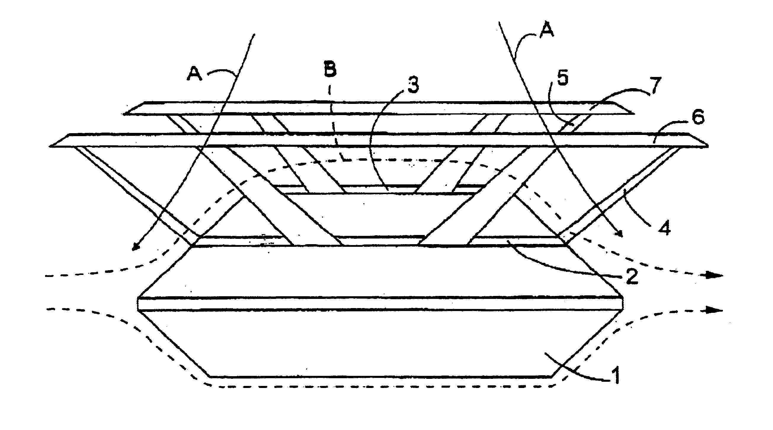
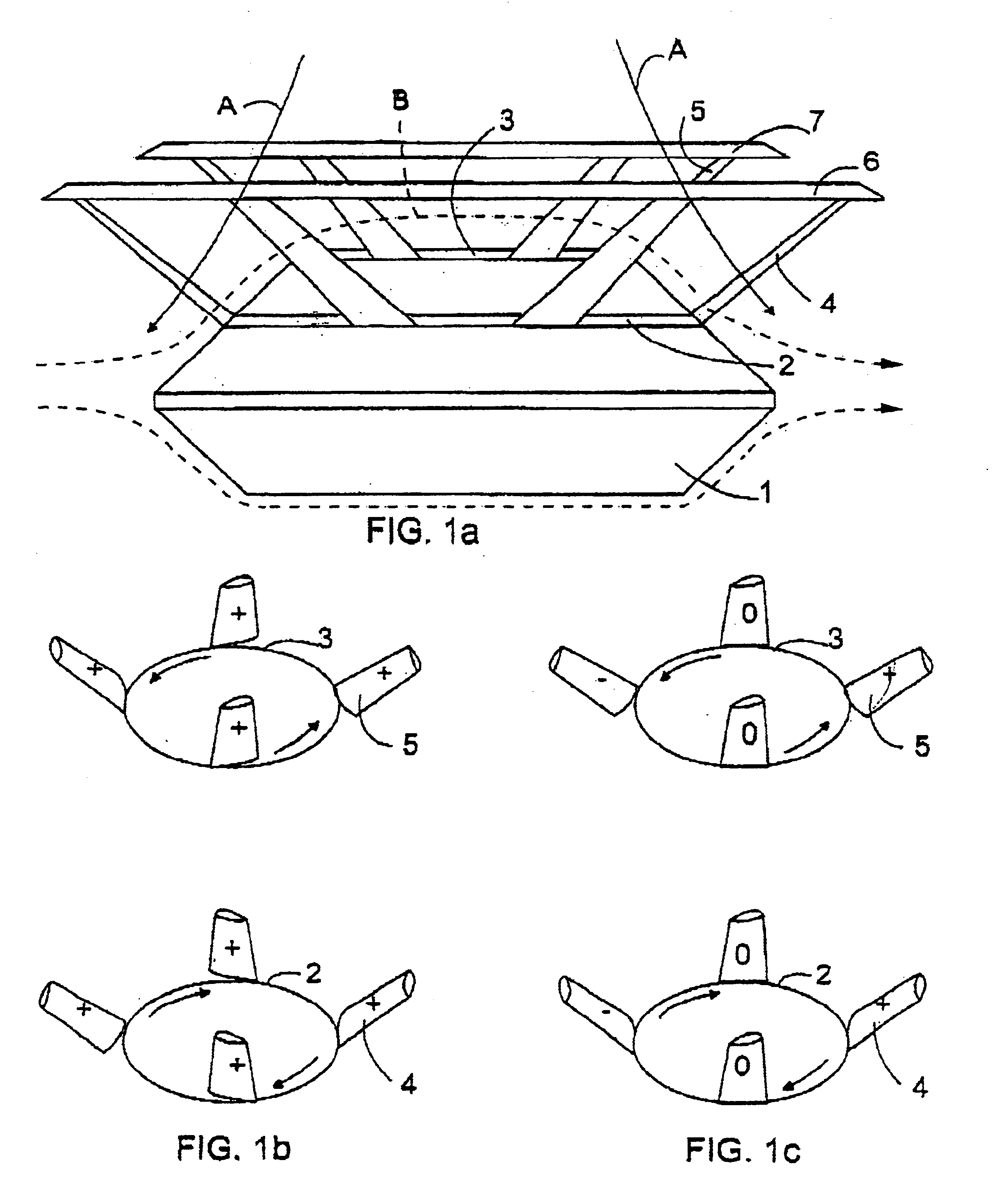
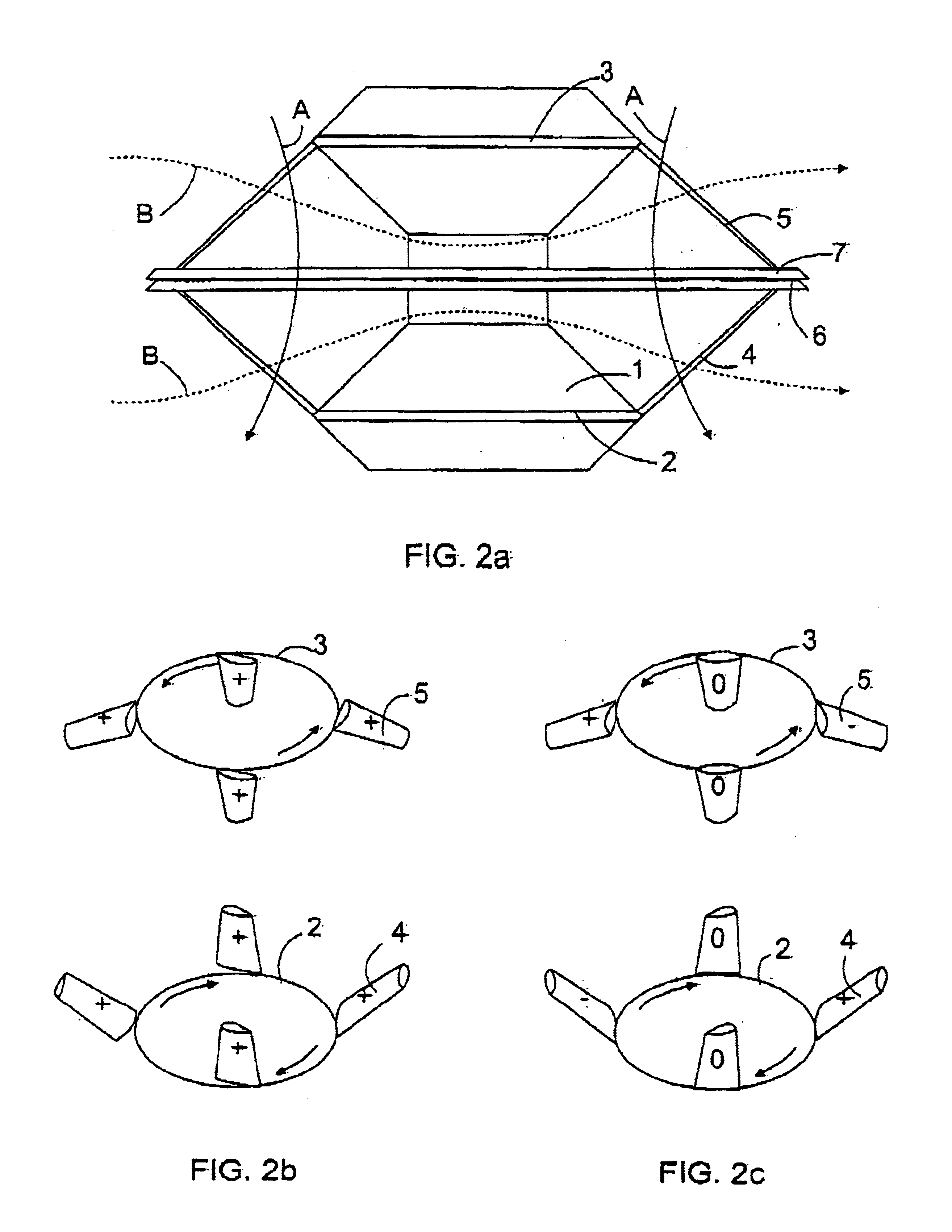
FIG. 1a shows an aircraft which has a body 1 having two rotating rotor rims 2 and 3 arranged to its upper part. The rotor rims 2 and 3 are arranged to rotate in opposing directions. Blades 4 and 5 are arranged to the rotor rims 2 and 3. The blades 4 and 5 are arranged at approximately 45° angle to the horizontal plane, whereby the blades 4 and 5 form a conical surface when rotating. The blades 4 and 5 are at their outermost ends connected with joint rings 6 and 7. The joint rings 6 and 7 can, in cross-section, be such that their top surface is curved and the lower surface is straight, whereby they can also produce an ascending force.

When taking off with the aircraft, the ascending force coefficient of all blades of both rotors is adjusted to be positive as shown in FIG. 1b. Air then flows as shown by arrows A in FIG. 1a, and the aircraft takes off. In this application, the definition that the ascending force coefficient of the blade is positive refers to the fact that the blade prod...


PUM


Abstract

An aircraft rotor and an aircraft which aircraft has a body and a rotor arranged to it, the rotor having at least two blades. The rotor is arranged to rotate around a substantially vertical axis. The blades are arranged in such a manner that, when rotating, they form a conical surface, whereby to provide ascending force, the ascending force coefficients of the blades are adjusted to be positive and to provide propulsive force, the ascending force coefficients of the blades on the forward side and on the rear side are adjusted to have opposite signs.

Description

BACKGROUND OF THE INVENTIONThe invention relates to an aircraft rotor which is arranged to rotate around a substantially vertical axis and which comprises at least two blades.Further, the invention relates to an aircraft which comprises a body and at least one rotor attached to the body and arranged to rotate around a substantially vertical axis and comprising at least two blades.Typically, helicopters have one rotor rotating around a substantially vertical axis, whereby the rotor blades rotate substantially horizontally. Helicopters have been presented, which comprise two rotors rotating around a substantially vertical axis, whereby the rotors can rotate in opposite directions. When the helicopter takes off, the blade angles are adjusted to be positive. After the take-off, when flying level, the blade angles of the rotor blades are adjusted as a function of the angle of rotation in such a manner that in the direction of travel, at the rear of the helicopter, the blade angle is grea...

Claims


Application Information

Patent Timeline
Patent Type & Authority Patents(United States)
IPC IPC(8): B64C27/32B64C39/00
CPCB64C39/001B64C27/32
Inventor KIRJAVAINEN, KARI
Owner NATURAL COLOR KARI KIRJAVAINEN
Why Eureka
Try Eureka