Bicycle frame

a bicycle frame and frame technology, applied in the field of bicycle frame and bicycle, can solve the problems of not being able to achieve the optimal response, loosening or damage vital joints, and rapid rider fatigue, and achieve the effect of reducing fatigue and increasing comfor

Inactive Publication Date: 2005-01-04
AMOS JEFFREY ERNEST
View PDF10 Cites 22 Cited by
  • Summary
  • Abstract
  • Description
  • Claims
  • Application Information

AI Technical Summary

Benefits of technology

The present invention seeks to provide a frame obviating at least some of the above disadvantages and providing a suspension system for bicycles which insulates the rider from shocks and impacts, thereby increasing comfort and reducing fatigue. The present invention further seeks to provide a bicycle comprising such a frame and suspension system.
According to a first aspect of the present invention, there is provided a bicycle frame comprising a first rigid member comprising means to mount a rear wheel, and means to mount a front wheel assembly, a second rigid member not connected directly to said first member and comprising means to mount a seat for a rider, and means to mount pedals, linkage means connecting pivotably between said first and said second rigid members, and shock absorbing means mounted between the linkage means and the first rigid member. A frame according to the present invention thus provides a suspension capable of absorbing large impacts whilst allowing a lightweight design. It is an important aspect of the invention that the first and second rigid members are not directly connected so that the components attached to one rigid member are made somewhat independent of movement occurring to components attached to the other rigid member. The positioning of the shock absorbing means allows for any type of gears as the suspension does not impinge on the drive / chain area. The distance between the seat and pedal axis remains fixed regardless of suspension movement. The design also helps to resist frame twisting which helps keep front and rear wheels in substantial alignment on rough terrain. The present invention allows the use of modern materials and manufacturing methods and also allows for aesthetically pleasing designs which are, of course, important in all areas of vehicle design. The linkage means may comprise a first trailing link connecting between an upper part of the second rigid member and a forward part of the first rigid member. The linkage means may further comprise a second leading link connecting between a lower part of the second rigid member and a rearward part of the first rigid member. The second leading link may be connected to the first rigid member via a bottom mount point. The bottom mount point may be one of a series of adjusting holes in order to allow angle adjustment of lower leading link to control frame response in heavy load situations. The force on the pedals is changed from rotating to linear by the action of the chain and so changing the angle of the lower leading links in relation to the top of the chain allows the pedal force to be used to partially suspend the rider and improve rear wheel traction by helping to hold the rear wheel in contact with the ground.
Preferably, the shock absorbing means is mounted to the first training link at a point intermediate between the ends thereof. A shock absorber is attached at its top end to the upper trailing link via a pivot bearing in one of a plurality of pivot points, and at a bottom end to each main frame element at one of a plurality of pivot points. The upper and lower points of attachment of the shock absorber may be moved to any one of the pivot points to tune the response of the frame to shocks and impacts. In this way the adjustment of the suspension may be highly variably without changing the basic components, such as the shock absorbing means.
The second rigid member may pass between the frame elements without being connected directly thereto. This allows a simple design which maintains the independence of the two rigid members.

Problems solved by technology

This could lead to rapid rider fatigue, and required robust construction or expensive materials of construction to reduce the risk of damage to the bicycle.
Sideways forces exerted on the rear wheel or on the frame can be transmitted through the shock absorber without being damped, and can tend to twist components out of alignment and may tend to loosen or damage vital joints, especially the pivot point between the swing arm and the mainframe.
The swingarm and rear wheel are constrained to move in an arc of a circle, which may not be an optimum response to an impact or shock.
Furthermore, a full-suspension frame is significantly heavier and more complicated to construct and maintain than a conventional frame.
However, it can be even heavier than the normal full-suspension frame, it is more complex to build and maintain, and the number of individual pivots and linkages greatly increase the chances of misalignment and bearing failure.
The weight distribution can be unpredictable, especially should the rider change from sitting on the saddle to standing up on the pedals.
Such a frame is relatively lightweight and simple, but it does not provide as much damping as the other forms of suspension, and it tends to be flexible laterally as well as vertically, leading to severe misalignment problems.

Method used


Image

  • Bicycle frame
  • Bicycle frame

Examples


Embodiment Construction

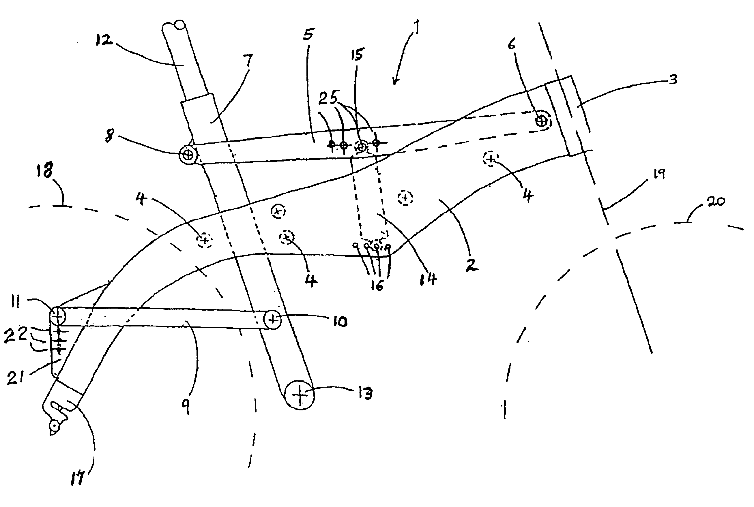
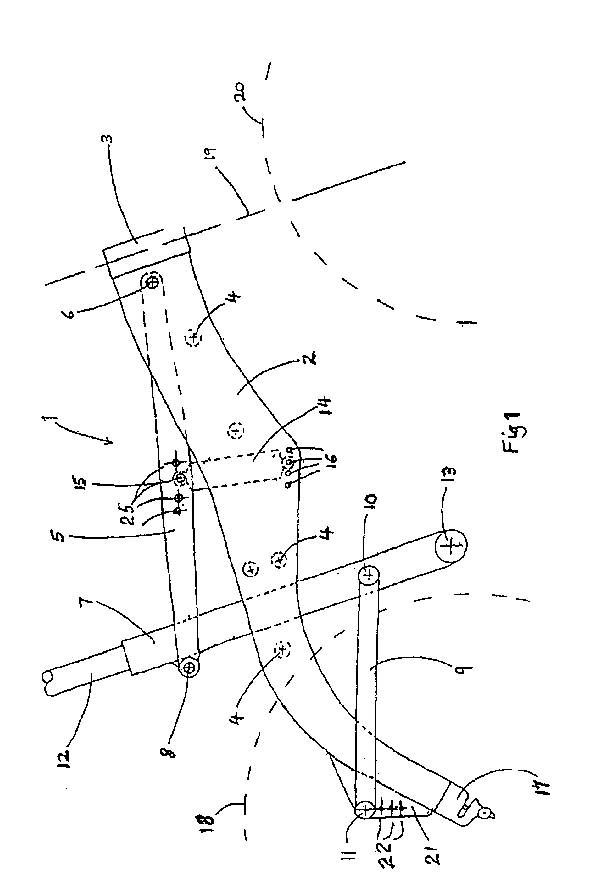
Referring now to the drawing, a frame 1 for a bicycle comprises a pair of main frame elements 2 (left and right hand pair; left hand element hidden in the view), which are connected and maintained at the required separation by a head set tube 3 and a plurality of spacers 4. The frame 1 comprises a first rigid member 1.

Each main frame element 2 bears at a lower end remote from the head set tube 3, a rear dropout system 17, to which a rear wheel indicated at 18, may be fitted. A set of gears (not shown) may also be fitted to the main frame element 2 adjacent the rear dropout system 17. The rear dropout system 17 may be exchangeable for a rear dropout system adapted to receive a disk-brake unit for the rear wheel 18. Alternatively or additionally, said lower end may also be adapted for carrying loads, such as panniers or camping gear.

A bicycle or mountain bike using the basic frame elements 2 has the rear wheel 18 fitted to the rear dropout system 17, and a front frame (not shown) incl...


PUM


Abstract

A bicycle frame includes a first rigid member with means for mounting a rear wheel and a front wheel assembly thereto. A second rigid member having means for mounting a seat post and pedals thereto is also provided. The second member is not connected directly to the first member but rather is linked by pivotable linkage to the first member. A shock absorber is preferably pivotably located between mounting points on the first and second rigid members. In a preferred embodiment a number of shock absorber mounting points are provided on the first member and first link in order to obtain an optimal shock absorber mounting position.

Description

BACKGROUND OF THE INVENTIONThe present invention relates to a bicycle frame and a bicycle including the bicycle frame. More particularly, but not exclusively, it relates to a frame for a bicycle with an improved suspension system.The invention is applicable to mountain bicycles; cross country bicycles; racing or touring bicycles. It is however, particularly relevant to mountain bikes and will be described herein in that context.Mountain bicycles were developed for riding across rough and steep terrain. The original designs featured rigid frames having configurations similar to those of conventional touring bicycles. The only means available to insulate the bicycle's rider and structure from shocks when crossing rough terrain was the use of large pneumatic tyres. This could lead to rapid rider fatigue, and required robust construction or expensive materials of construction to reduce the risk of damage to the bicycle.It is known to provide shock absorbers, incorporated into the front ...

Claims


Application Information

Patent Timeline
Patent Type & Authority Patents(United States)
IPC IPC(8): B62K19/00B62K19/34B62K19/36B62K3/10B62K3/00
CPCB62K3/10B62K19/36B62K19/34
Inventor AMOS, JEFFREY ERNEST
Owner AMOS JEFFREY ERNEST
Why Eureka
Try Eureka