
Orthopedic shoulder weight halter

a technology of orthopedic body and halter, which is applied in the field of orthopedic body weight devices, can solve the problems of weight being applied pulling from a broad area and being displaced, and achieve the effect of increasing the amount of weigh

Inactive Publication Date: 2005-01-04
HANNERS ERNEST M +1
View PDF9 Cites 10 Cited by
  • Summary
  • Abstract
  • Description
  • Claims
  • Application Information

AI Technical Summary

Benefits of technology

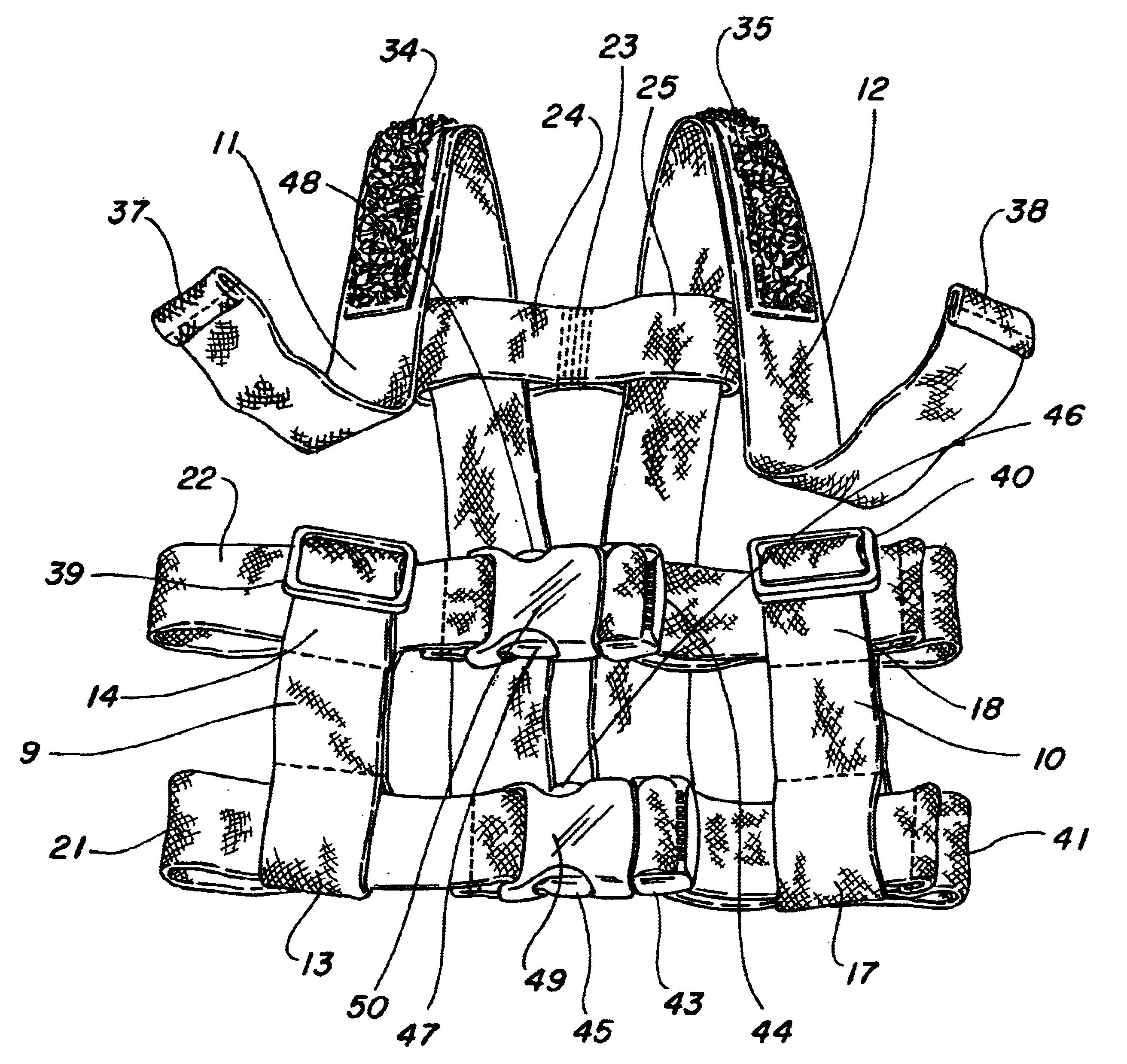
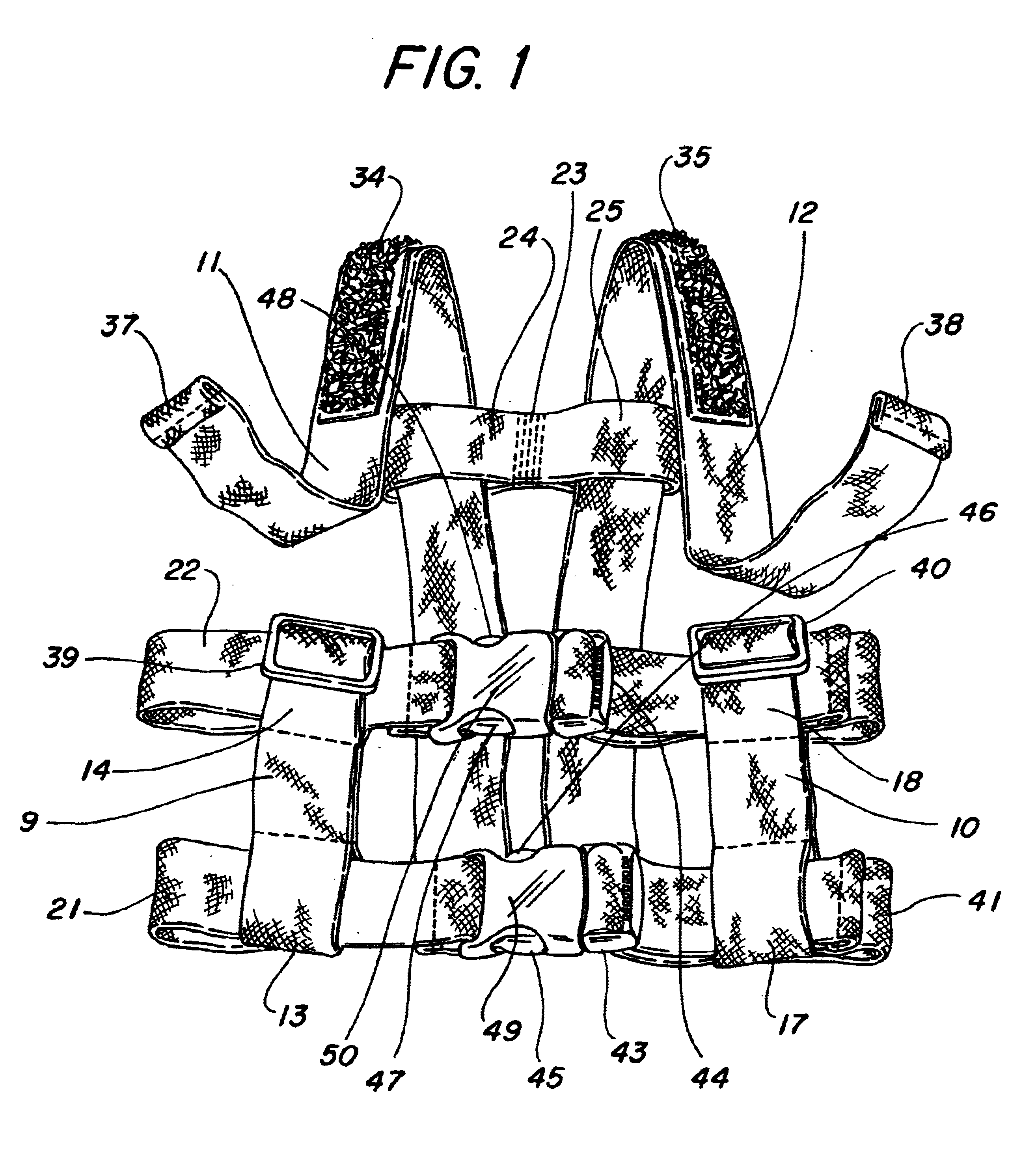
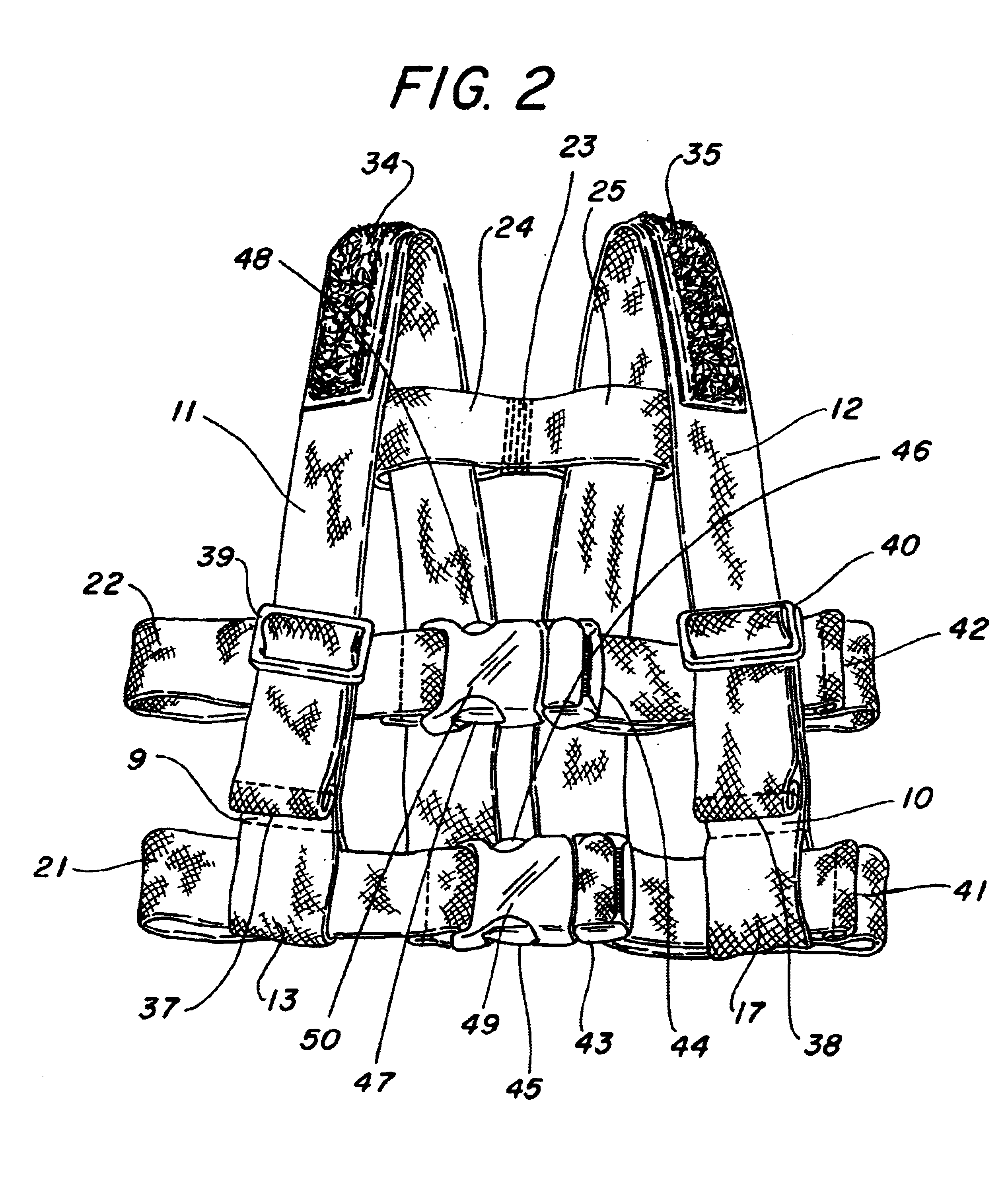
The orthopedic shoulder weight halter to be described here is widely adjustable to accommodate a variety of body sizes. Shoulder straps and front support straps are sewn to create loops that allow waist and chest straps to slide through them for positioning the shoulder straps and front support straps to maintain a proper alignment. The shoulder straps are easily adjustable in length by use of double-D rings which are located on the front support straps, and through which the shoulder straps are threaded. Quick release buckles with double-D rings offer easy width adjustments to the waist and chest straps, and also allow the halter to be donned or taken off quickly.
An adjustable butterfly strap containing a hook side fastening material strip, such as hook side Velcro, is attached to the back section of both shoulder straps. The butterfly strap attaches tightly to the loop side fastening strips sewn onto the shoulder straps. The butterfly strap adjusts the width of the shoulder straps and holds the shoulder straps in place to prevent the weight(s) from sliding off the shoulder. Various other means can be used to accomplish the same effect as the butterfly strap. A simple strip of hook side fastening material or a strip of hook side fastening material sewn onto a simple strap will accomplish the same end.
A hook side fastening material strip is sewn on one side of the weight(s) used in this invention, and a loop side fastening material strip is sewn onto the other side of the same weight(s). This allows the weight(s) to be attached to the other shoulder strap(s), and also allows the weights to be stacked one on top of the other. This stacking method is used to increase the amount of weight as needed. The weights are preferably made of a nylon covered neoprene material, but may also be made with most fabrics. With this invention, the weight is being applied directly to the shoulder area, giving maximum benefit.

Problems solved by technology

Such configurations result in problems in that the weight being applied is pulling from a broad area and is displaced throughout the shoulder, back, neck, waist, and chest areas, rather than being focused mostly on the shoulder itself.

Method used


Image

  • Orthopedic shoulder weight halter
  • Orthopedic shoulder weight halter
  • Orthopedic shoulder weight halter

Examples


Embodiment Construction

Looking at FIGS. 1 through 6 simultaneously, it is seen that the orthopedic shoulder weight halter is essentially comprised of a right shoulder strap 11, left shoulder strap 12, a waist strap 21, a chest strap 22, a right support strap 9, a left support strap 10, and a weight 26 that attaches to one of the shoulder straps. The lengths of the shoulder straps 11 and 12 are adjustable by being threaded through the double-D rings 39 and 40 sewn into the front support straps 9 and 10, the overlapping respective ends 37 and 38 of the straps allowing plenty of extra strap length for suitable adjustment of strap length.

Sewn into right support strap 9 are front loops 13 and 14. Similarly, sewn into left shoulder strap 10 are front loops 17 and 18. Sewn into right shoulder strap 11 are back loops 15 and 16. Similarly, sewn into left shoulder strap 12 are back loops 19 and 20.

Through the support strap bottom loops 13 and 17, and through the shoulder strap bottom back loops 15 and 19, passes an...


PUM


Abstract

An orthopedic shoulder weight halter and corresponding weight(s) are described which allow one or more weights to be attached to shoulder straps by fastening material strips. Fourteen points of adjustment in the halter allow for a universe of different torso sizes. The harness possesses two shoulder straps, two front support straps, a waist strap, a chest strap, an upper back / chest strap, four double-D rings and two quick release buckles. The harness and the weight(s) can be easily put on or taken off of the wearer.

Description

BACKGROUND OF THE INVENTIONThis invention fits into the general category of orthopedic devices and more particularly into the specific category of orthopedic body weight devices.It is well known that persons with upper motor neuron problems, brain injury or illesses, spinal cord injury, multiple sclerosis, and other neurological dysfunctions often experience tremors of the body. It is also known that applying weight directly on the shoulders will reduce tremors and some involuntary spasticity associated with these and similar conditions that cause such tremors.Up until now the standard attempt to satisfy this problem of applying orthopedic weights to the body have featured regular vest configurations with pockets sewn into the vest such that weights can then be inserted into the pockets. However, most weight pockets sewn into such vests are at the waist and / or chest areas rather than at the shoulder areas. Such configurations result in problems in that the weight being applied is pu...

Claims


Application Information

Patent Timeline
IPC IPC(8): A63B21/065A63B21/06A61H1/00
CPCA63B21/065A63B21/0603A61H1/006
Inventor HANNERS, ERNEST M.HANNERS, JUDY A.
Owner HANNERS ERNEST M
Learn More