

Method and apparatus for testing an electronic pet containment transmitter
a technology transmitter, which is applied in the field of electronic pet containment systems, can solve the problems of pet containment systems not offering the end-user an easy way to verify the correct operation of the transmitter, and the inability to determine whether the boundary is active and functioning properly
- Summary
- Abstract
- Description
- Claims
- Application Information
AI Technical Summary
Benefits of technology
Problems solved by technology
Method used
Image

Examples
Embodiment Construction
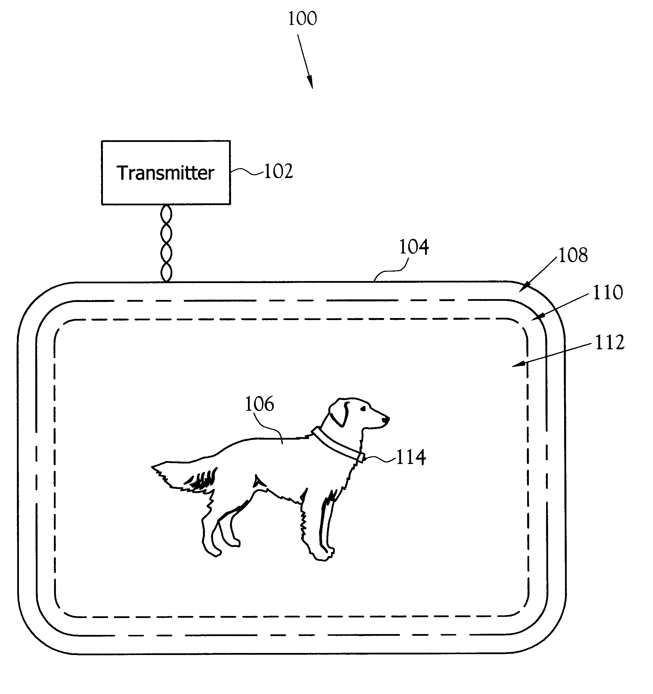
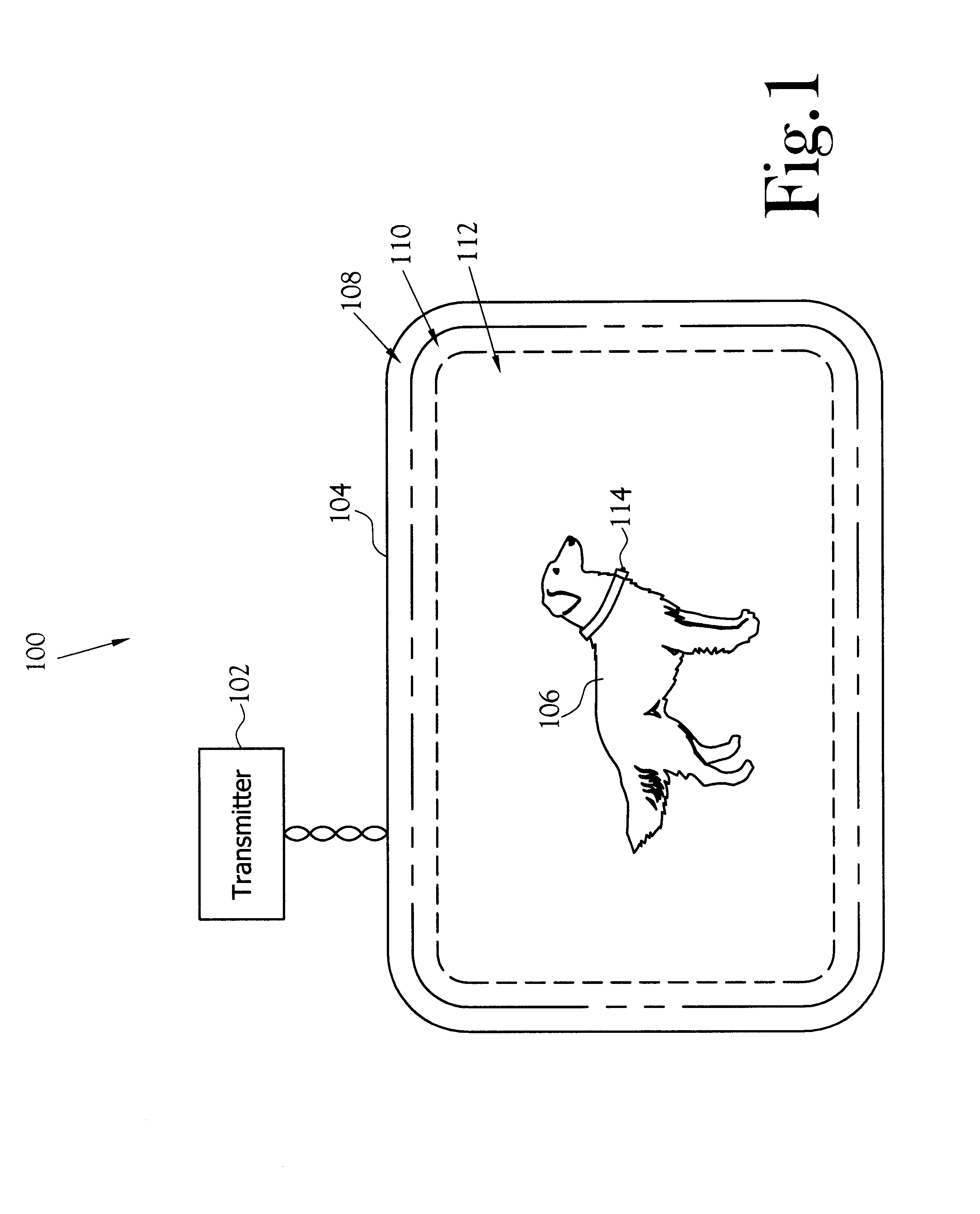
A method and apparatus for testing the proper operation of an electronic pet containment transmitter, or electronic pet containment system tester is described and shown in the figures. The transmitter includes an internal short loop antenna that is used to activate the receiver unit when it is brought into close proximity of the transmitter.
FIG. 1 illustrates one embodiment of an electronic animal containment system 100. The electronic animal containment system 100 includes a transmitter 102 that produces an electromagnetic containment signal, which defines the containment area 104. A wire-loop connected to the transmitter 102 defines the boundary of the containment area 104 and serves as a broadcast antenna for the containment signal. The animal 106 is contained within the containment area 104 through the use of the receiver unit 114, which is carried by the animal 106. The containment area 104 defines three zones. The first zone is a safe zone 112 where the animal 106 receives no ...
PUM
 Abstract
Description
Claims
Application Information