A method for foreign object debris detection

a foreign object and debris detection technology, applied in the field of remote detection systems, can solve the problems of difficulty in limiting foreign object debris to a specific shape, color or material property, inability to reliably control the manual process, etc., and achieve the effect of more robust and accurate filters

Active Publication Date: 2019-11-21
ARGOSAI TEKNOLOJI ANONIM SIRKETI
View PDF0 Cites 25 Cited by
  • Summary
  • Abstract
  • Description
  • Claims
  • Application Information

AI Technical Summary

Benefits of technology

[0014]The present invention proposes more robust and accurate filters obtained using convolutional deep neural networks to solve the foreign object debris problem and overcome the challenges encountered in the pipeline. The main advantage of this technique is that the convolutional network filters learn the surface characteristics for obtaining an efficient and diligent edge and line identification specific to the surface under scrutiny.

Problems solved by technology

The diversity in the causes and properties of the foreign object debris, results in difficulties constraining it to a specific shape, color or material property.
The foreign object debris could often be small and even harmless.
However, such a manual process is not always reliable and prone to human error which cannot be tolerated.
Moreover, such techniques endanger the continuity of the airport operations and take a lot of time, in addition to increasing the risk of accidents especially on busy airports.
The Sobel and Scharr filters however are rather limited in terms of obtaining image edge characteristics.
Using radar technology has the risk of interfering with the existing airport and aircraft equipment.
The main drawback of this technique resides on the fact that the inspection on the desired detection area cannot be performed constantly, since the plane traffic on the desired area has to be stopped in order to allow the passage of the vehicle carrying the 3D laser sensor.

Method used


Image

  • A method for foreign object debris detection
  • A method for foreign object debris detection
  • A method for foreign object debris detection

Examples


Embodiment Construction

[0019]Accompanying figures are given solely for the purpose of exemplifying a FOD detection system, whose advantages over prior art were outlined above and will be explained in brief hereinafter.

[0020]The figures are not meant to delimit the scope of protection as identified in the claims nor should they be referred to alone in an effort to interpret the scope identified in said claims without recourse to the technical disclosure in the description of the present invention.

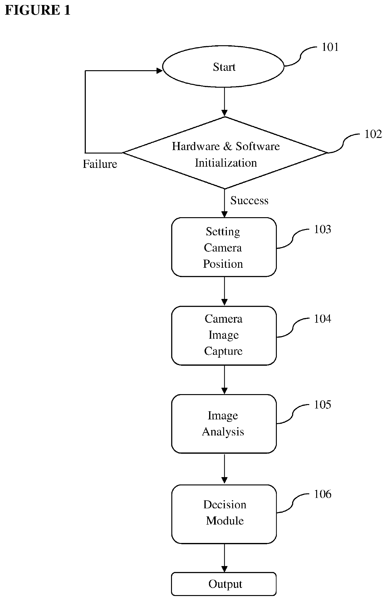
[0021]FIG. 1 illustrates the general pipeline of the operation from start until the end of decision module according to the present invention.

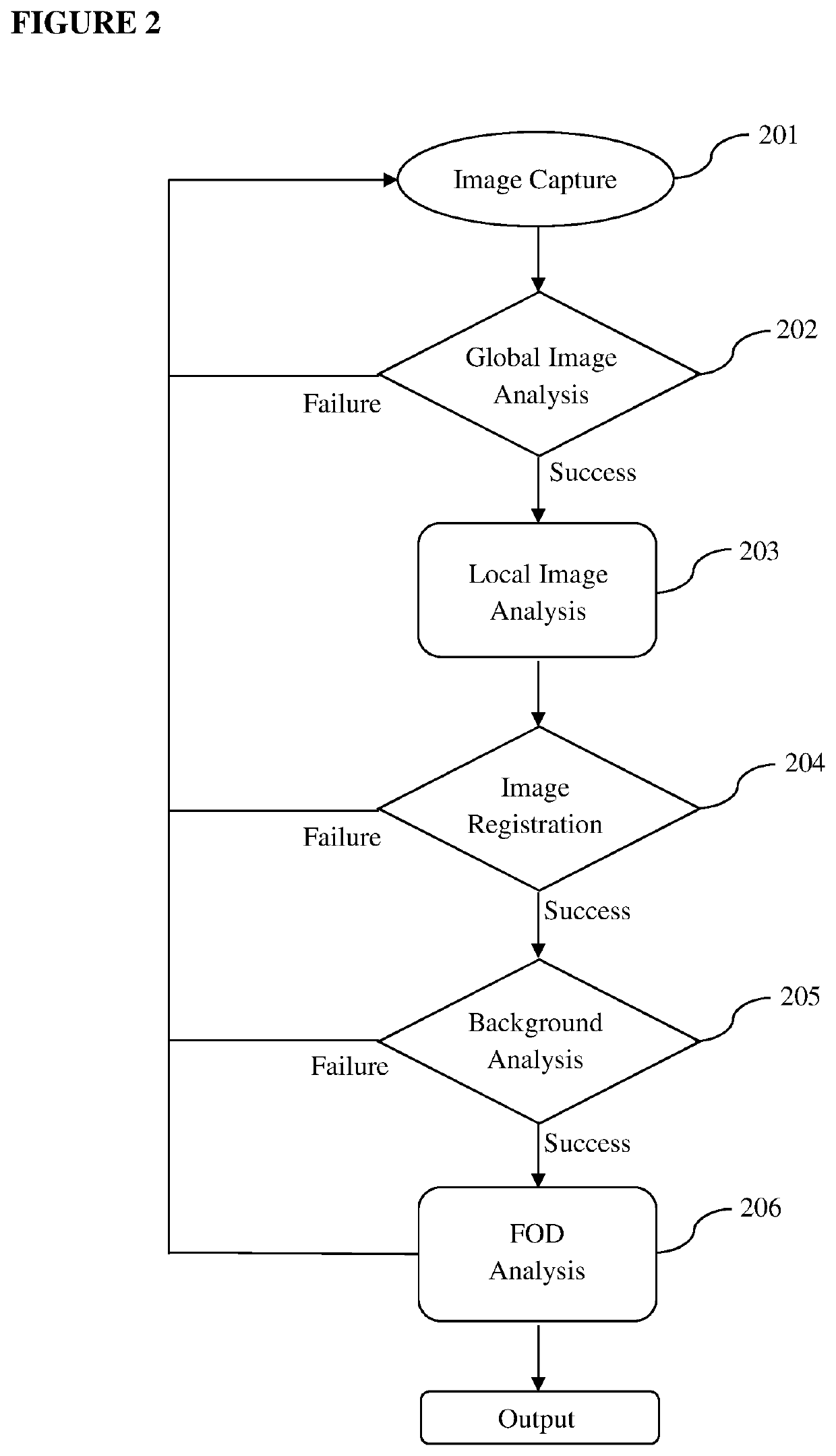
[0022]FIG. 2 illustrates the general architecture of the image analysis pipeline from image capture until the end of FOD analysis module according to the present invention.

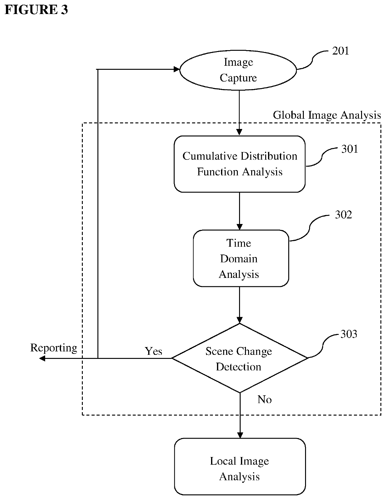
[0023]FIG. 3 demonstrates the details of Global Image Analysis module according to the present invention.

[0024]FIG. 4 demonstrates the details of Local Image Analysis module according to the present invent...


PUM


Abstract

This invention discloses a system and method for detection of foreign object debris (FOD) on the areas of including but not limited to the airport runways, taxiways, aprons and adjacent areas. The invention makes use of single or multiple passive optical sensors monitoring the areas for signal acquisition, a database and a processing unit to further analyze the captured optical signal in order to detect the presence; and in case of the detection of the foreign debris in various threat levels, creating an alert for the removal thereof; depending on variables such as the estimated area and foreign object size and visual characteristics.

Description

FIELD OF THE INVENTION[0001]This invention discloses a remote detection system for monitoring the surface areas including, but not limited to, airport runways, taxiways, aprons and adjacent areas to detect the occurrence of an FOD in real time and with utmost accuracy.BACKGROUND OF THE INVENTION[0002]Foreign Object Debris (FOD) is any substance, debris or article alien to a vehicle or system that can potentially cause harm, particularly in an aerospace setting. FOD could occur on runways, taxiways, aprons and adjacent areas for various reasons such as a particle coming from a construction site, a ground vehicle, an aircraft or even an animal. The diversity in the causes and properties of the foreign object debris, results in difficulties constraining it to a specific shape, color or material property.[0003]The ability to automatically distinguish a foreign object on the operation-critical surfaces on the airports has a vital importance for the safe execution of aviation protocols in...

Claims


Application Information

Patent Timeline
Patent Type & Authority Applications(United States)
IPC IPC(8): G06K9/00G06K9/46G06K9/62G06T7/33G08G5/00
CPCG06T2207/30232G06K9/6215G06T7/33G06K9/4623G08G5/0026G06K9/00771G06T2207/20084G06V20/588G06V20/58G06V10/451G06V10/82G06V10/761G06F18/22G06V20/52
Inventor TASLI, HUSEYIN EMRAHKARADENIZ, MERIH ALPHANKOSE, AZIZ
Owner ARGOSAI TEKNOLOJI ANONIM SIRKETI
Why Eureka
Try Eureka