
Fastenerless connection for output device

a technology of output device and fastener, which is applied in the direction of coupling device connection, electrical apparatus casing/cabinet/drawer, instruments, etc., can solve the problem of significant over-dimension of mounting plate, and achieve the effect of convenient mounting arrangemen

Inactive Publication Date: 2005-01-04
PITTWAY CORP
View PDF17 Cites 108 Cited by
  • Summary
  • Abstract
  • Description
  • Claims
  • Application Information

AI Technical Summary

Benefits of technology

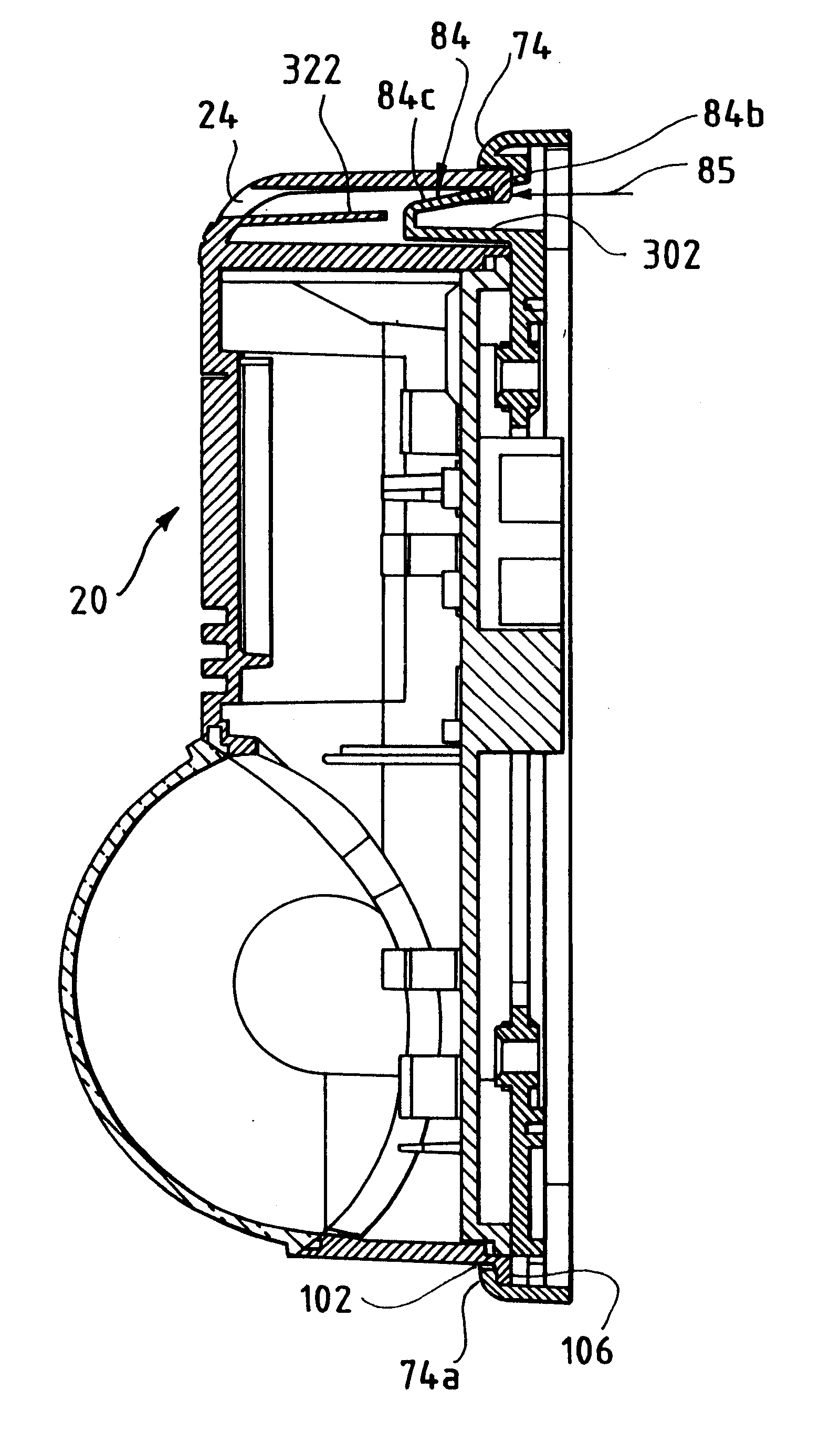
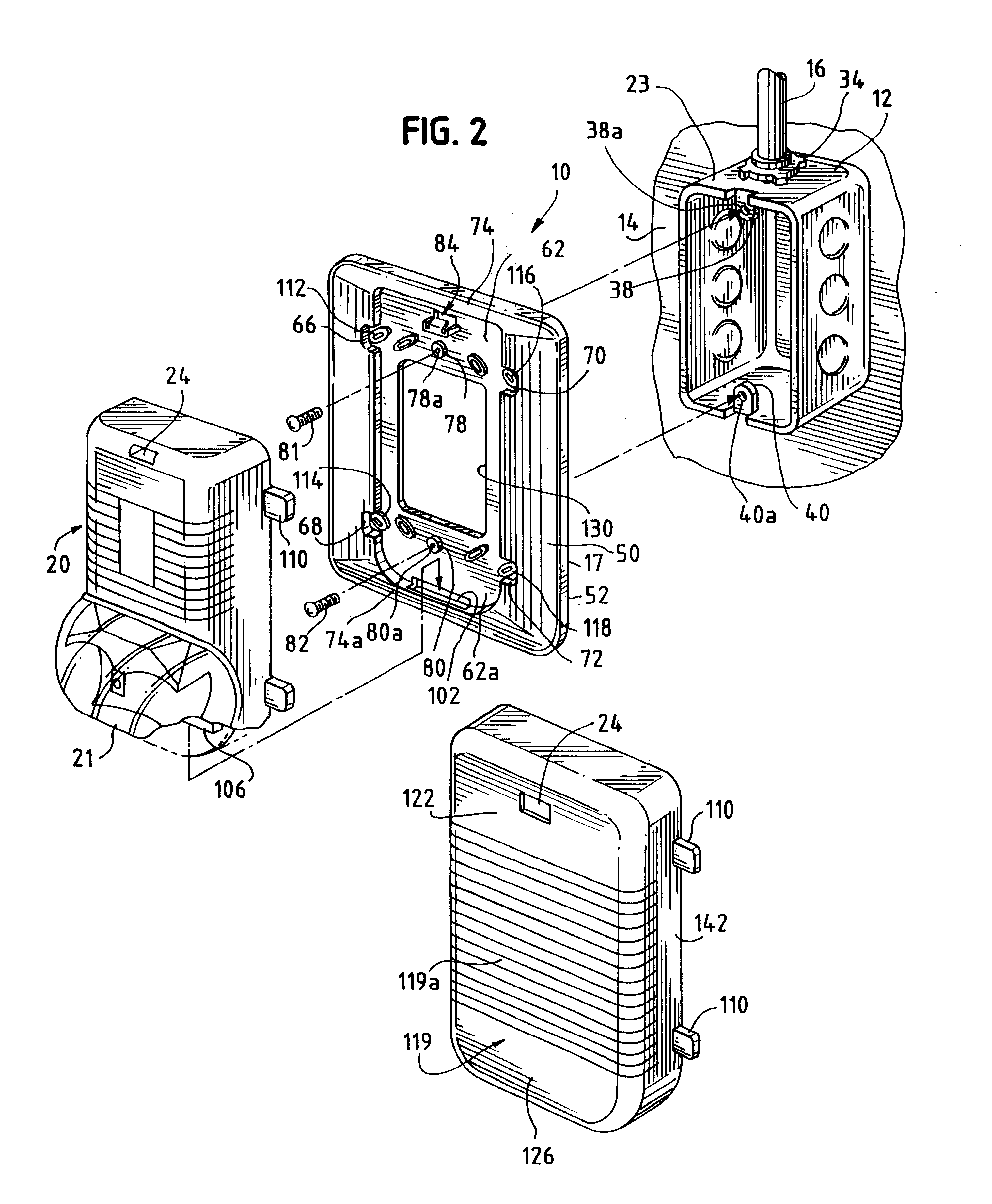
The mounting plate of the present invention is attachable to a wall recessed electrical box or a surface mounted electrical box. The mounting plate provides an easy mounting arrangement for an alarm unit or module or other electrical device to be attached thereto. The mounting plate and associated alarm units or module include snap engagement parts which allow the alarm unit or module to be attached to the mounting plate without any need for fasteners or tools.
The arrangement of the invention provides for a quick and easy installation or exchange of an alarm unit, emergency light or other electrical device onto a pre-installed mounting plate.
When mounted to a recessed electrical box, the electrical box is effectively concealed. Additionally, the screws which connect the mounting plate to the electrical box can be covered by the respective alarm unit, or emergency light, thereby improving the overall appearance of the assembly.
In addition to being architecturally appealing, the mounting plate is also functional. When the alarm unit or emergency light is removed from the mounting plate, the mounting plate provides an enclosure and protection to signal wires located within the otherwise open electrical box.
While the alarm unit or emergency light is being exchanged, tested, or during construction, the conduit and electrical box is clearly designated as dedicated to signal wires for alarms to reduce any confusion between signal conduits and signal electrical boxes and electrical power conduits and electrical power electrical boxes. In this way, the alarm system components can be more clearly demarcated.

Problems solved by technology

The mounting plates can be significantly oversized when compared to an open face of either electrical box.

Method used


Image

  • Fastenerless connection for output device
  • Fastenerless connection for output device
  • Fastenerless connection for output device

Examples


Embodiment Construction

While the present invention is susceptible of embodiment in various forms, there is shown in the drawings and will hereinafter be described a presently preferred embodiment, with the understanding that the present disclosure is to be considered as an exemplification of the invention, and is not intended to limit the invention to the specific embodiment illustrated.

The present invention is an improvement to the mounting plate and module system described in U.S. Ser. No. 08 / 953,122, filed Oct. 17, 1997 and herein incorporated by reference.

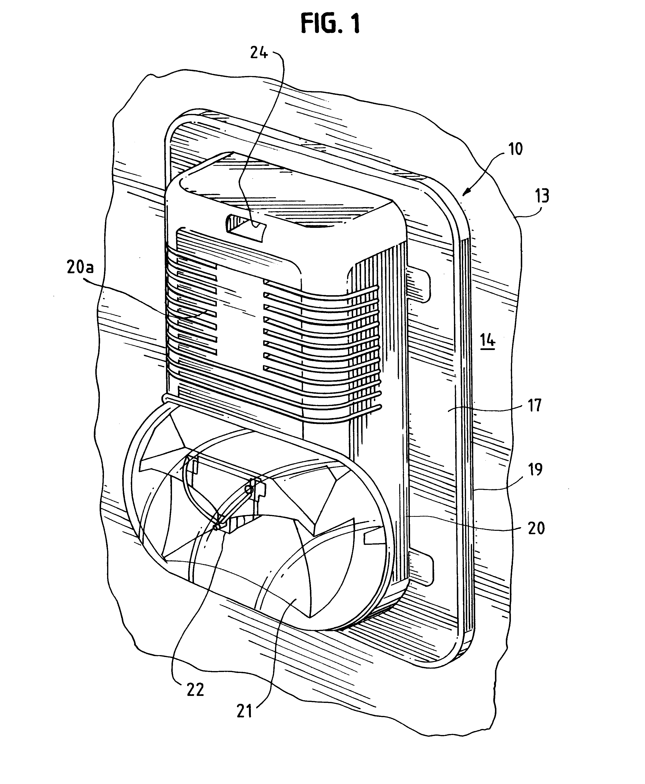
FIG. 1 illustrates an alarm unit assembly 10 installed onto an electrical box 12 (shown in FIG. 2) which is recessed into a wall 13 from a wall surface 14.

A mounting plate 17 is connected to the electrical box. The mounting plate has a surrounding edge 19 which is adjacent to the wall surface 14.

A strobe light alarm unit 20 is mounted to the mounting plate 17. The alarm unit includes a lens 21 covering a lamp 22. In the illustrated embodiment, the st...


PUM


Abstract

A plastic mounting plate closes a electrical box which delivers wires to an alarm unit or emergency light or the like. The alarm unit is mounted to the mounting plate by a snap connection and a tab-in-slot connection, without requiring the use of a tool. The mounting plate is connected to the electrical box by screws which engage threaded holes provided by the electrical box. The mounting plate can be mounted to either a single-wide electrical box or a double-wide (4×4) electrical box and provides corresponding holes for connection to either box. An alternate mounting plate for a single-wide electrical box is also provided.

Description

FIELD OF THE INVENTIONThe present invention relates to alarm units and associated devices which mount to electrical boxes. More particularly, the present invention relates to a mounting plate for attaching an alarm unit module to either a recessed or a surface mounted electrical box.BACKGROUND OF THE INVENTIONFor purposes of safety and security, alarm or security related electric devices can be positioned throughout a building or structure. The devices can constitute detectors such as smoke detectors, or can be annunciators such as audible fire and security alarms, or can include emergency lights.The detectors can include motion detectors or other intruder alarms. Additionally, other local area monitoring devices which sense an ambient condition or provide a local alarm can be mounted at locations throughout a building or other structure.In the case of a building having unfinished walls, such as a warehouse, such devices are typically attached to surface mounted electric wire electr...

Claims


Application Information

Patent Timeline
IPC IPC(8): G08B7/00G08B7/06G08B5/22G08B5/36H02G3/14
CPCG08B7/062H02G3/14
Inventor DAVIDSON, CURTIS R.
Owner PITTWAY CORP
Learn More