Active matrix type display apparatus and portable terminal using the same

a display apparatus and active matrix technology, applied in the direction of non-linear optics, static indicating devices, instruments, etc., can solve the problems of inability to reduce the power consumption of the output section and the 1-bit mode, and achieve the effect of not consuming power and reducing power consumption

Inactive Publication Date: 2005-01-04
JAPAN DISPLAY INC
View PDF8 Cites 34 Cited by
  • Summary
  • Abstract
  • Description
  • Claims
  • Application Information

AI Technical Summary

Benefits of technology

The present invention is about a display apparatus that can reduce power consumption by placing only a number of circuit portions into an active state when a low gradation mode is set, which uses a smaller number of gradations than a normal mode. This results in a reduction of power consumption and improved efficiency of the display apparatus.

Problems solved by technology

The technical problem addressed in this patent is to reduce the power consumption of a display apparatus in a portable terminal, particularly in the standby period, using a polycrystalline silicon TFT structure of the driving circuit integration type. The invention aims to provide an active matrix type display apparatus that can apply the 1-bit mode to reduce power consumption while using the polycrystalline silicon TFT structure.

Method used


Image

  • Active matrix type display apparatus and portable terminal using the same
  • Active matrix type display apparatus and portable terminal using the same
  • Active matrix type display apparatus and portable terminal using the same

Examples


Embodiment Construction

In the following, embodiments of the present invention are described in detail with reference to the drawings.

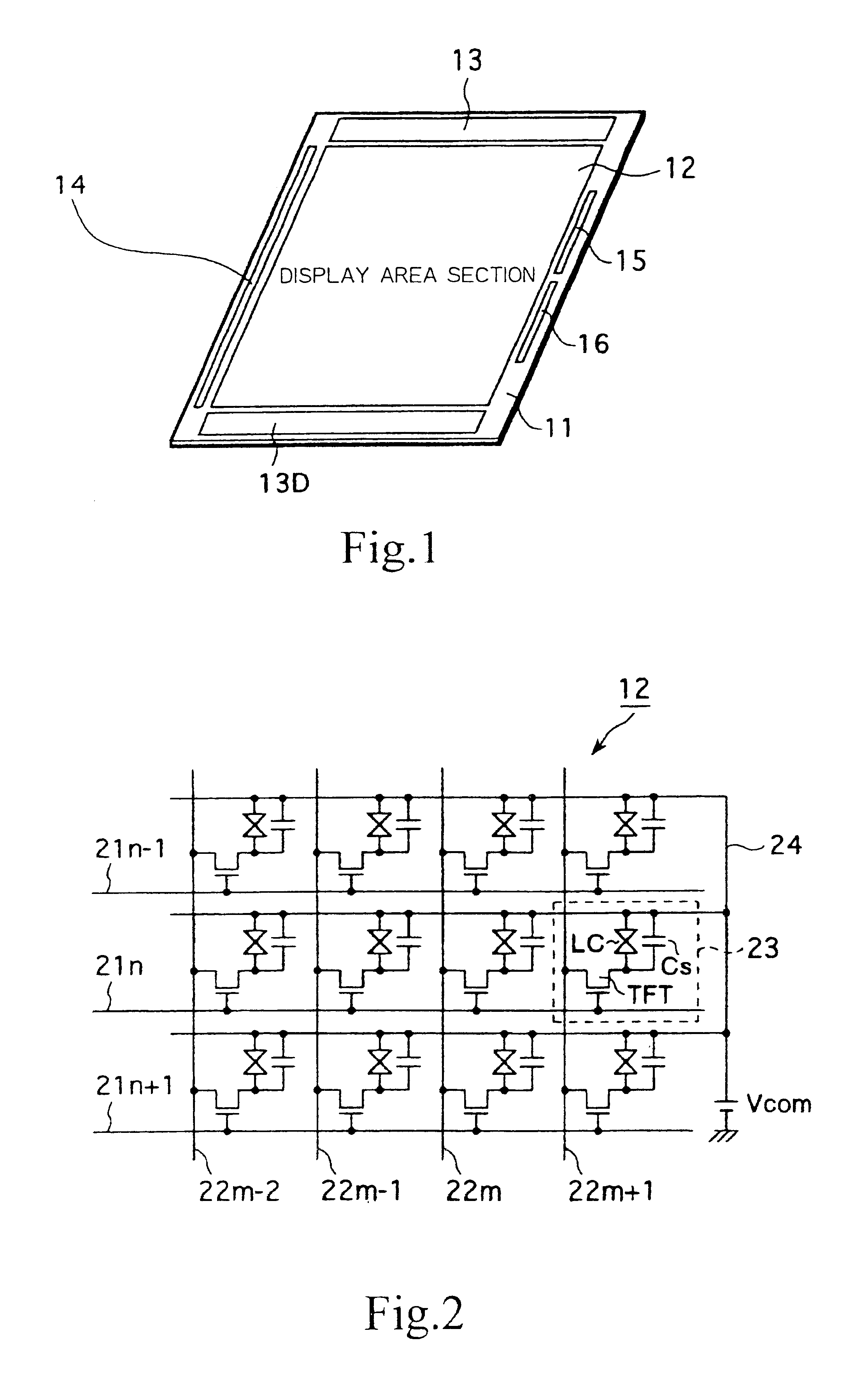
FIG. 1 is a view of a schematic configuration showing an example of a configuration of a display apparatus according to the present invention. Here, the description is given taking, a case wherein the present invention is applied, for example, to a liquid crystal active matrix type display apparatus in which a liquid crystal cell is incorporated as an electro-optical element of each pixel.

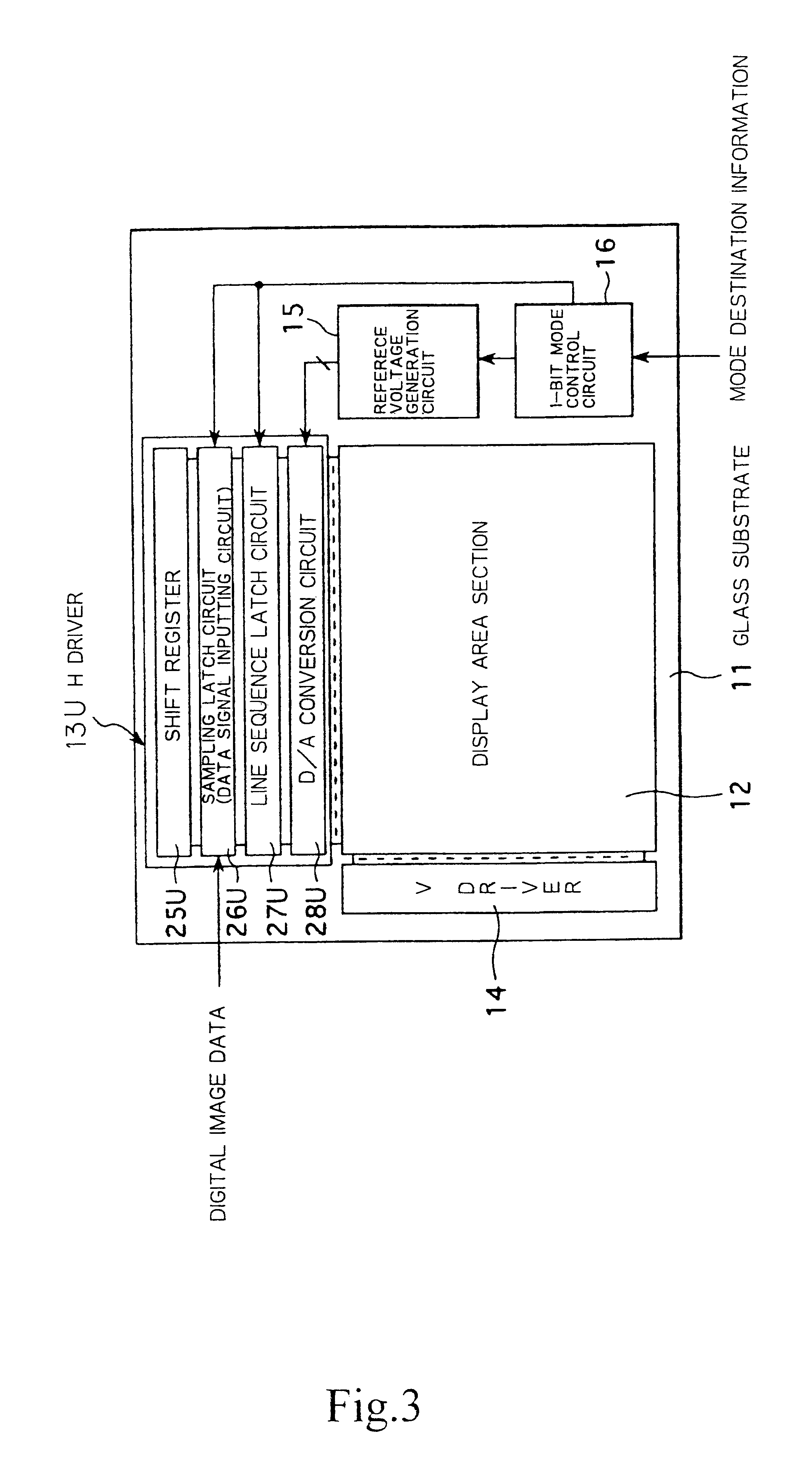
Referring to FIG. 1, a display area section 12 wherein a large number of pixels each including a liquid crystal cell are disposed in a matrix manner, a pair of upper and lower H drivers (horizontal driving circuits) 13U and 13D and a V driver (vertical driving circuit) 14, as well as a reference voltage generation circuit 15 for generating a plurality of reference voltages and a 1-bit mode control circuit 16, are integrated on a transparent insulation substrate, for example, a glass substra...


PUM


Abstract

In order to solve a subject that a polycrystalline silicon TFT liquid crystal display apparatus of the driving circuit integration type cannot adopt a technique for reducing the power consumption by an output section, according to the present invention, for example, a sampling latch circuit which composes a horizontal driving circuit (data line driving circuit) of an active matrix type display apparatus is configured such that, when a 1-bit mode (2-gradation mode) is set, a control signal A of the “H” level and another control signal B of the “L” level (low level) are outputted from a 1-bit mode control circuit (16) to place only AND circuits (31-2 and 32-2) corresponding to the most significant bit (MSB) into a passage permitting state to place only latch circuits (35-2 and 36-2) of the MSB into a data writing permitting state (active state) while the remaining latch circuits (35-0, 35-1, 36-0 and 36-1) are placed into a data writing inhibiting state (inactive state).

Description


Claims


Application Information

Patent Timeline
Owner JAPAN DISPLAY INC
Why Eureka
Try Eureka