
Heat dissipation from a hand-held portable computer

a portable computer and heat dissipation technology, applied in the direction of lighting and heating apparatus, electric apparatus casings/cabinets/drawers, instruments, etc., can solve the problems of user fire or burn injury, device failure, permanent damage to the device, etc., and achieve the effect of dissipating heat from the internal componen

Inactive Publication Date: 2005-01-04
VULCAN PORTALS
View PDF10 Cites 17 Cited by
  • Summary
  • Abstract
  • Description
  • Claims
  • Application Information

AI Technical Summary

Benefits of technology

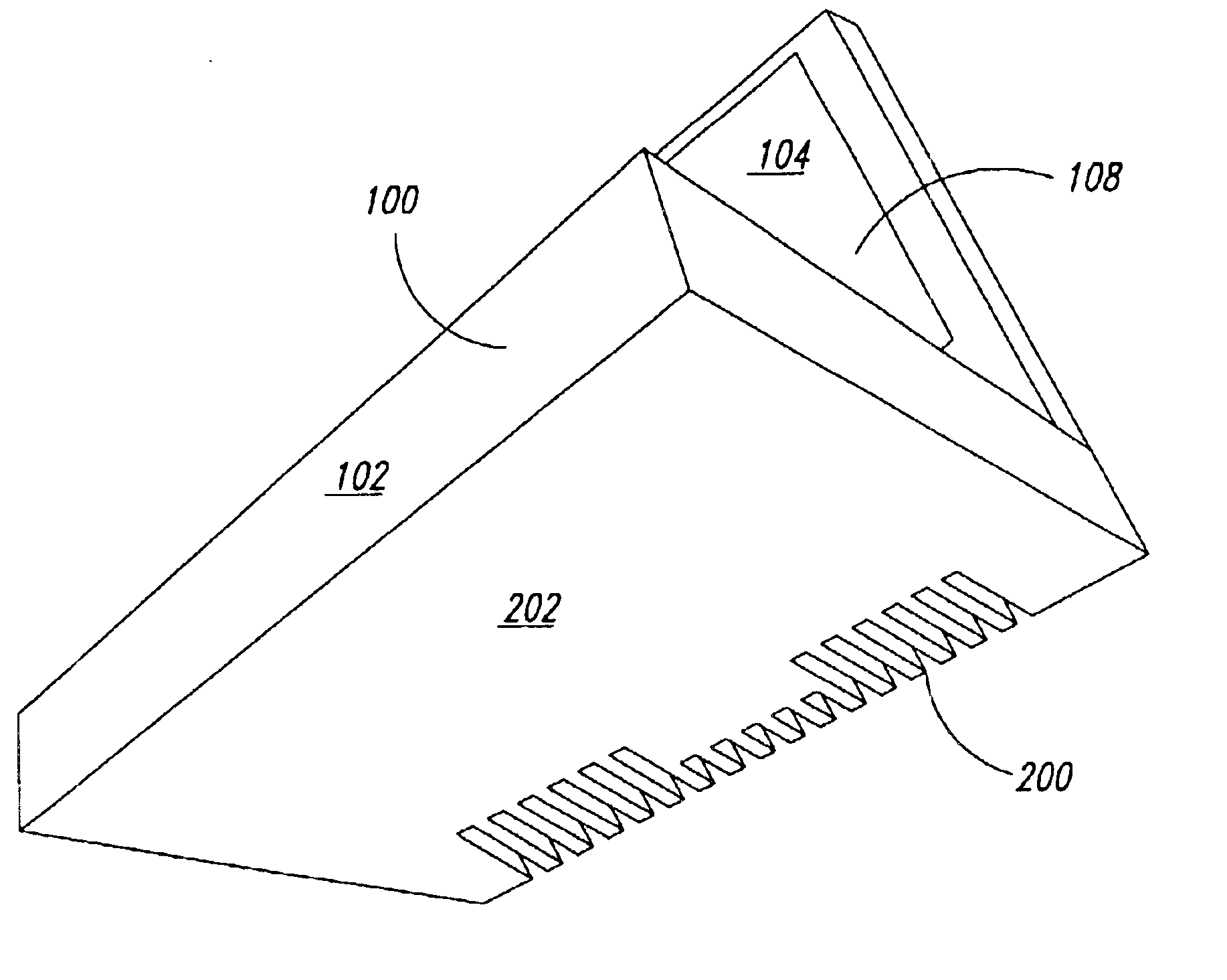
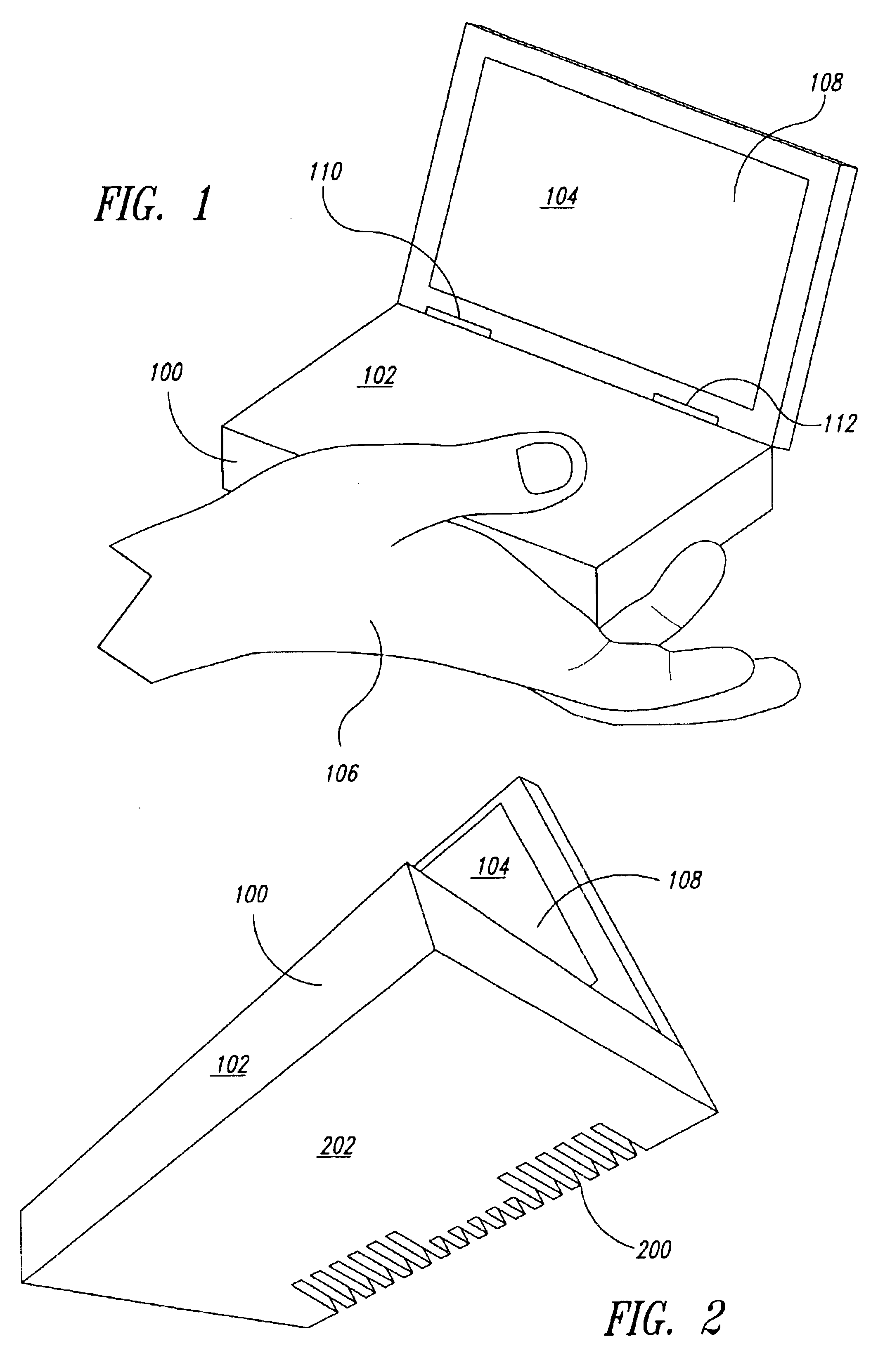
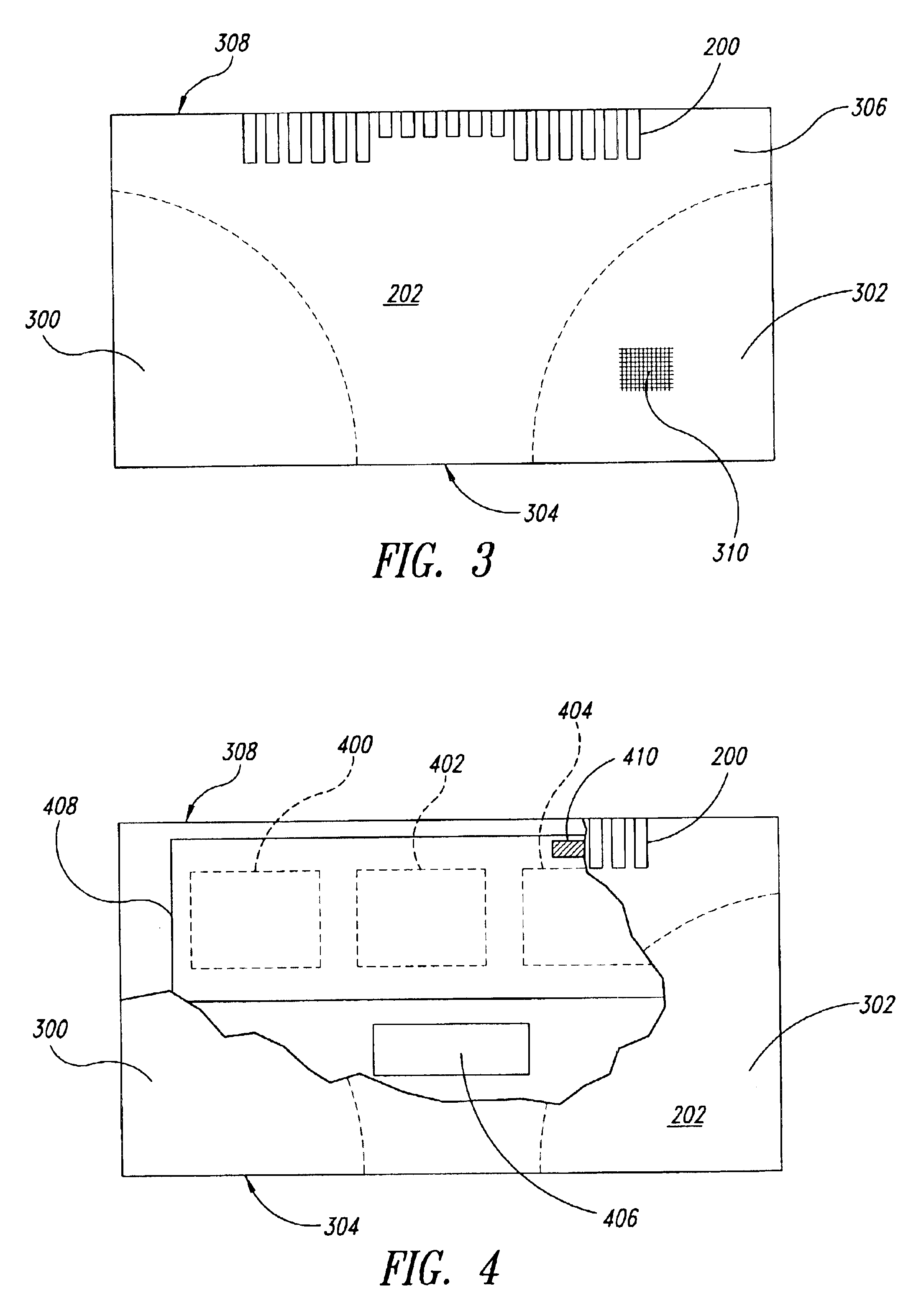
One aspect of the invention provides an apparatus that includes a casing having first and second areas. The first area is a region where the casing is hand-held during operation. The apparatus includes at least one internal component located inside of the casing and that is a source of heat. A heat dissipative element is thermally coupled to the internal component to dissipate the heat from the internal component, with the heat dissipative element being located proximate to the second area and being distanced from the first area.

Problems solved by technology

Failure to properly dissipate the heat can lead to device failure, permanent damage to the device, and potential fire or burn injury to a user.
Newer smaller personal computers (PCs), such as sub-notebooks and ultra-portable computers, have three primary issues that influence their design and operation.
First, as compared to conventional-sized PCs, it is more difficult to build extremely small devices while still leaving sufficient room for airflow.
Second, it is difficult and undesirable to have a fan running in the device, due to size, weight, power, and noise issues.
Third, these smaller devices have a significantly smaller surface area (in many cases less than ¼ of the area of a conventional-sized PC) to dissipate heat, which results in far higher temperatures on surfaces, thereby potentially causing burning (of the user's skin, for instance) or external fire.
Therefore, many solutions have opted for lower performance and lower voltage operation to solve these heat dissipation issues.
This is unfortunate for users because such devices are losing the opportunity to provide higher performance.

Method used


Image

  • Heat dissipation from a hand-held portable computer
  • Heat dissipation from a hand-held portable computer
  • Heat dissipation from a hand-held portable computer

Examples


Embodiment Construction

Embodiments of techniques to remove or reduce heat from a hand-held device, such as a portable computer, via dissipation of the heat from non-hand-held areas, regions, or zones of the portable computer are described herein. In the following description, numerous specific details are given to provide a thorough understanding of embodiments of the invention. One skilled in the relevant art will recognize, however, that the invention can be practiced without one or more of the specific details, or with other methods, components, materials, etc. In other instances, well-known structures, materials, or operations are not shown or described in detail to avoid obscuring aspects of the invention.

Reference throughout this specification to “one embodiment” or “an embodiment” means that a particular feature, structure, or characteristic described in connection with the embodiment is included in at least one embodiment of the present invention. Thus, the appearances of the phrases “in one embod...


PUM


Abstract

Heat is removed from a small hand-held portable computer by dissipating the heat from surfaces that are not typically held by the user during hand-held operation. The heat is dissipated from fins located at a rear underside casing of the portable computer. Heat-generating internal electronic components or their heat sinks are placed in close proximity to the fins. Heat may also be dissipated from the backside of the display screen. The dissipation of the heat allows the portable computer to operate at higher frequencies.

Description

BACKGROUND OF THE INVENTION1. Field of the InventionThe present disclosure relates generally to heat transfer and heat dissipation techniques, and in particular but not exclusively, relates to removal of heat generated from a hand-held device, such as a portable computer, by transferring and dissipating the heat from non-hand-held regions of the device.2. Description of the Related ArtMany laptops or other hand-held devices create 10-30 watts of power from processors, graphics systems, disk drives, memory systems, display drivers, backlights, and other components. This generated power is in the form of heat that must be moved away from the heat-generating chip(s) to the outside of the device. Failure to properly dissipate the heat can lead to device failure, permanent damage to the device, and potential fire or burn injury to a user.Modern laptops use heat-pipes, heat sinks, and fan(s) to pull the heat to the outside surface or air. Newer smaller personal computers (PCs), such as su...

Claims


Application Information

Patent Timeline
Patent Type & Authority Patents(United States)
IPC IPC(8): G06F1/20H05K7/20
CPCG06F1/203H05K7/20409G06F2200/203
Inventor FLECK, ROD G.CHEBELEU, LIVIUS D.
Owner VULCAN PORTALS
Learn More