
System and method for distributing multicasts in virtual local area networks

a virtual local area network and multicast message technology, applied in the field of computer networks, can solve the problems of consuming valuable network bandwidth as well as processor and memory resources, affecting network performance, and severe compromising of the throughput of the trunk link, so as to achieve efficient multicast message distribution

Inactive Publication Date: 2005-01-04
CISCO TECH INC
View PDF53 Cites 288 Cited by
  • Summary
  • Abstract
  • Description
  • Claims
  • Application Information

AI Technical Summary

Benefits of technology

Briefly, the invention is directed to a system and method for efficiently distributing multicast messages within a computer network that includes one or more regions having a plurality of virtual local area network (VLAN) domains. According to the invention, a multicast network device (MND) having a plurality of interfaces includes a multicast controller for distributing multicast messages among the subscribing VLAN domains defined within the respective regions. The multicast controller, which is in communicating relationship with the interfaces, includes a VLAN assignment engine that is configured to assign responsibility for the VLAN domains within a given region to the extent there are multiple MNDs coupled to that region. That is, each MND coupled to the same VLAN region will be responsible for a different set of the respective VLAN domains. The multicast controller also accesses a multicast tag source to create a plurality of novel VLAN tags for efficiently distributing multicast messages.

Problems solved by technology

Depending on the number of VLAN designations associated with a given multicast message, this may severely compromise the throughput on this trunk link.
In addition, the replication of multicast messages, which must then be distributed by the bridges and switches, consumes valuable network bandwidth as well as processor and memory resources.
As a result, network performance may suffer.

Method used


Image

  • System and method for distributing multicasts in virtual local area networks
  • System and method for distributing multicasts in virtual local area networks
  • System and method for distributing multicasts in virtual local area networks

Examples


Embodiment Construction

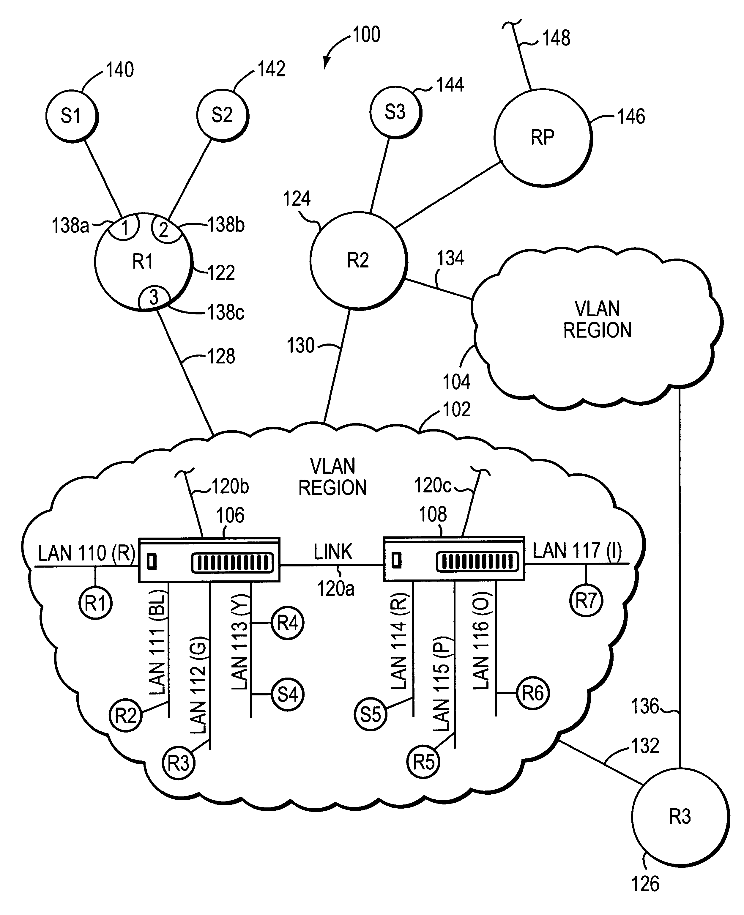
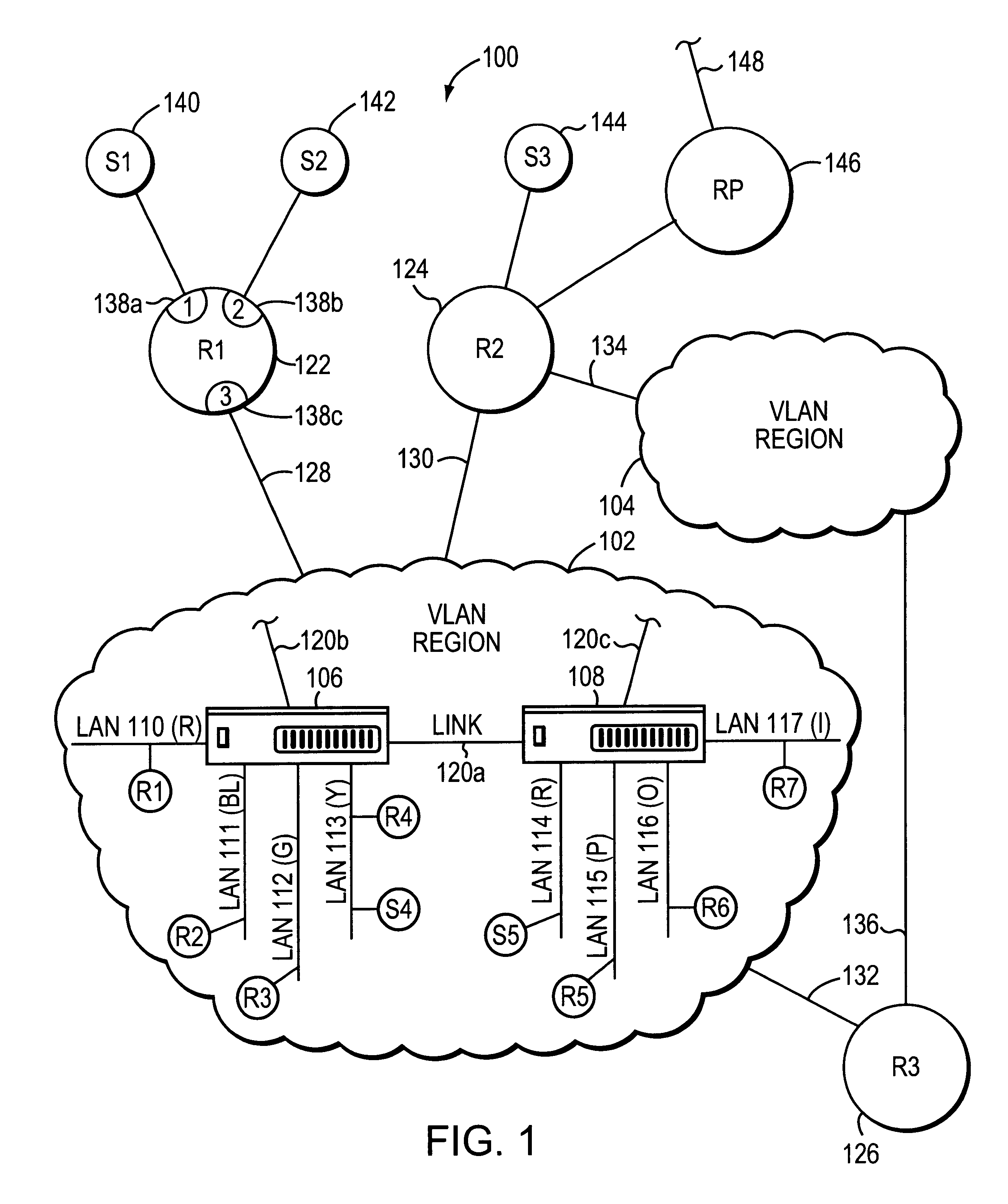
FIG. 1 is a block diagram of an illustrative computer network 100. The network 100 includes a plurality of virtual local area network (VLAN) regions or clouds, such as VLAN regions 102 and 104, each of which includes a plurality of VLAN domains. More specifically, each VLAN region 102, 104 includes a plurality local area networks (LANs) to which end stations and / or servers may be coupled. These LANs and network entities, moreover, may be interconnected by one or more intermediate network devices, such as bridges and switches. VLAN region 102, for example, includes at least two switches 106, 108, which have a plurality of ports (not shown). Coupled to the ports of each switch 106, 108 are a plurality of LANs, such as LANs 110-113, and 114-117, respectively. Switches 106, 108 are also coupled together through trunk ports via link 120a. Each switch 106, 108 may include other trunk ports coupled to additional links 120b, 120c for interconnection with other intermediate network devices. ...


PUM


Abstract

The invention relates to a system and method for efficiently distributing multicast messages within computer networks configured to have one or more virtual local area network (VLAN) domains. A multicast network device (MND), having a plurality of interfaces, includes a multicast controller for efficiently distributing multicast messages among subscribing entities associated with various VLAN domains. The multicast controller, which is in communicating relationship with the interfaces, includes a VLAN assignment engine for assigning responsibility for the VLAN domains to the extent there are multiple MNDs. The multicast controller also accesses a multicast tag source to establish a plurality of novel VLAN tags for efficiently distributing multicast messages, including a sub-regional Multicast VLAN Identifier (MVLAN-ID) that encompasses all of the VLAN domains for which the respective MND is responsible, and one or more color-limited MVLAN-IDs that encompass all of the VLAN domains for which the MND is responsible except for one. The multicast controller then tags multicast messages with its sub-regional or a color-limited MVLAN-ID depending on whether the message is considered internal or external by the respective MND. The tagged messages are then forwarded for distribution to the subscribers associated with the various VLAN domains.

Description

FIELD OF THE INVENTIONThe present invention relates generally to the field of computer networks, and more specifically, to the efficient distribution of multicast messages in computer networks having virtual local area network associations.BACKGROUND OF THE INVENTIONOrganizations, including businesses, governments and educational institutions, rely on computer networks to share and exchange information. A computer network typically comprises a plurality of entities interconnected by a communications media. An entity may consist of any device, such as a computer, that sources (i.e., transmits) and / or receives messages over the communications media. A common type of computer network is a local area network (“LAN”) which typically refers to a privately owned network within a single building or campus. LANs typically employ a data communication protocol (LAN standard), such as Ethernet, FDDI or Token Ring, that defines the functions performed by the data link and physical layers of a co...

Claims


Application Information

Patent Timeline
IPC IPC(8): H04L12/56H04L12/46H04L12/18
CPCH04L12/18H04L45/16H04L45/00H04L45/04H04L12/4645H04L12/185
Inventor TANG, CHENGNAIK, CHICKAYYA G.
Owner CISCO TECH INC
Learn More