Sealed terminating device

a terminating device and sealing technology, applied in the direction of securing/insulating coupling contact members, coupling device connections, contact members penetrating/cutting insulation/cable strands, etc., can solve the problems of unprotected terminating devices, subscriber no longer being able to access the communications network, and significant expens

Inactive Publication Date: 2005-01-04
CORNING OPTICAL COMM LLC
View PDF10 Cites 72 Cited by
  • Summary
  • Abstract
  • Description
  • Claims
  • Application Information

AI Technical Summary

Problems solved by technology

Unprotected terminating devices may fail when subjected to a voltage or current surge.
When a terminating device fails, the subscriber is no longer able to access the communications network.
Further, the service provider must d

Method used


Image

  • Sealed terminating device
  • Sealed terminating device
  • Sealed terminating device

Examples


Embodiment Construction

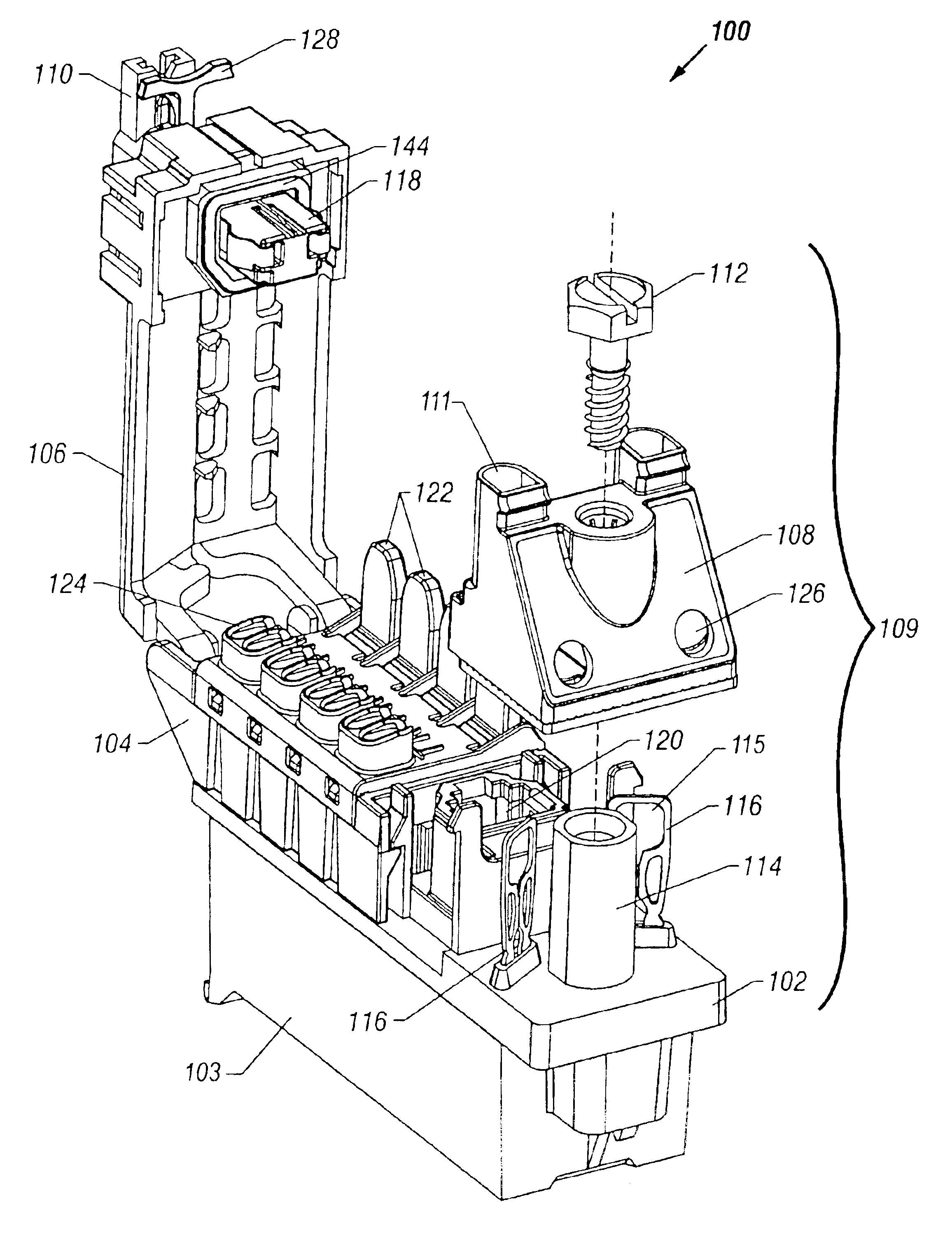
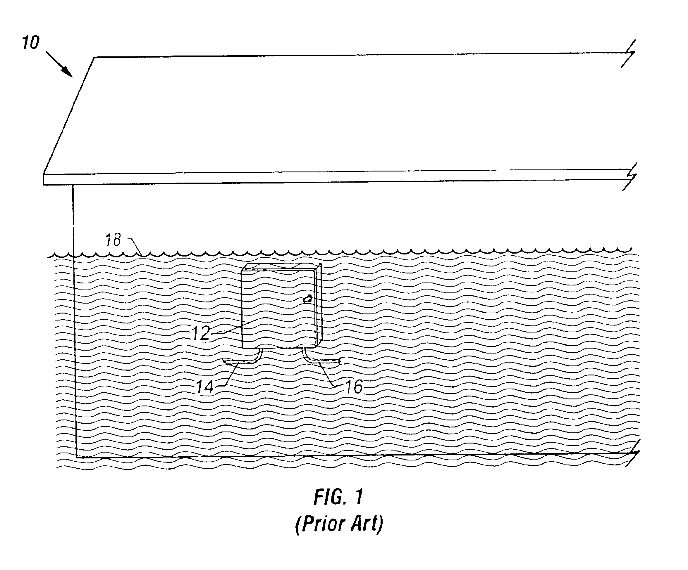
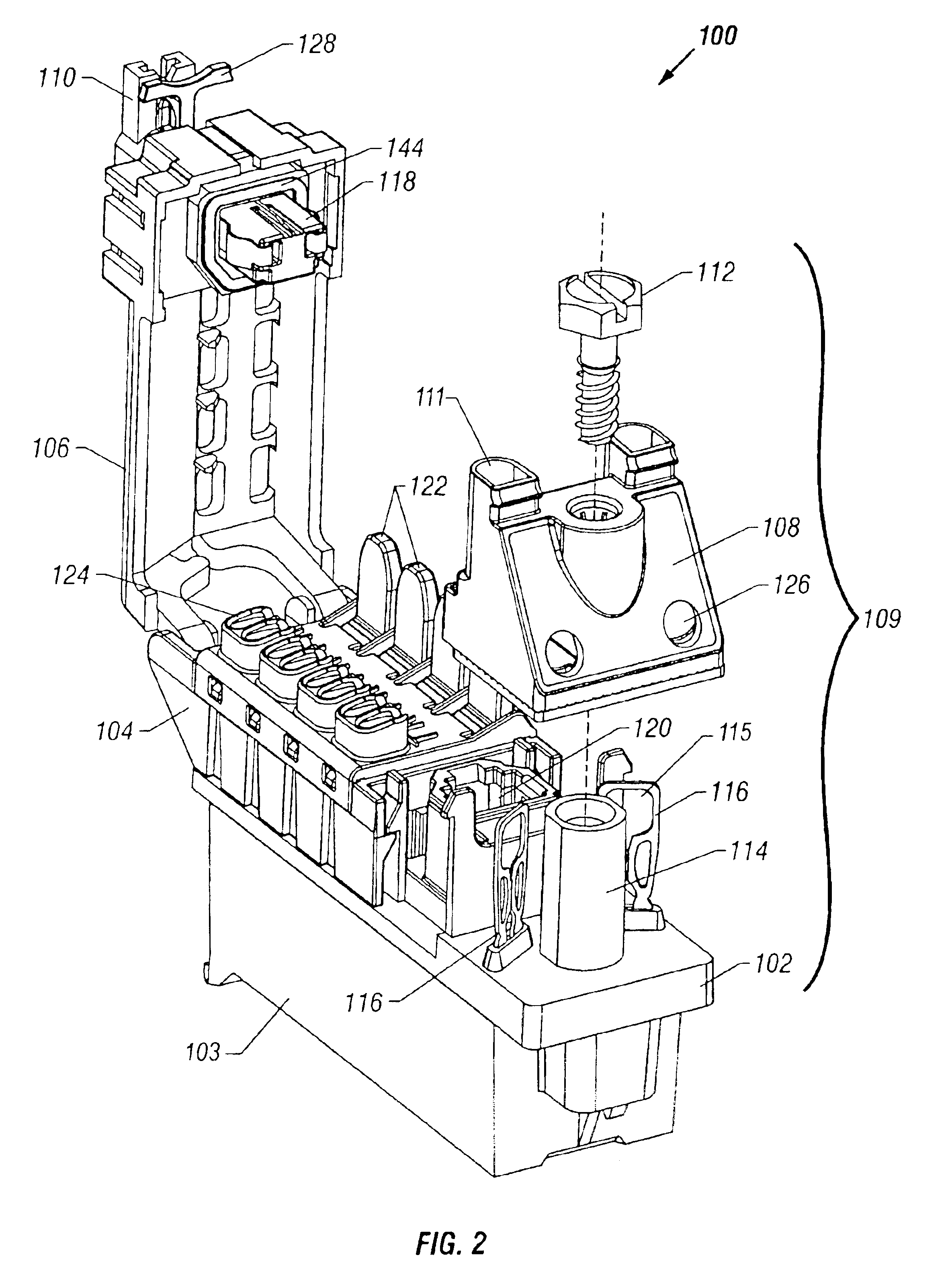
The invention relates to a terminating device for interconnecting service provider wiring 14 with subscriber wiring 16 (FIG. 1). A terminating device 100 constructed in accordance with the invention is shown in FIG. 2. The terminating device 100 may be any apparatus or device for interconnecting service provider wiring 14 with subscriber wiring 16, such as a line module, PTD, or the like. For purposes of example only and not for limitation, the terminating device shown and described herein is a line module 100 that is housed within a NID 12 (FIG. 3) to serve as a demarcation point between the service provider wiring 14 and the subscriber wiring 16 in a telecommunications network. The line module 100 includes a base 102 and a customer bridge 104 mounted on the base. The base 102 is positioned over and attached to a generally hollow electronics module 103 that may contain electronic circuitry, such as a printed circuit board or a telephone half-ringer. In another embodiment, the elect...


PUM


Abstract

A terminating device for interconnecting service provider wiring with subscriber wiring includes a base, a customer bridge, a removable cover and insulation displacement contacts for terminating the service provider wiring and the subscriber wiring. The insulation displacement contacts for the subscriber wiring are housed within the customer bridge and terminate the subscriber wiring by moving an actuating arm from a disconnected position to a connected position. The insulation displacement contacts for the service provider wiring terminate the service provider wiring by moving a stuffer from a disconnected position to a connected position. The cover includes a locking slide having a movable clasp for deterring unauthorized access to the customer bridge, while permitting authorized access. A plug on the cover and a jack on the base each have a resilient seal that telescope together to effectively seal test contacts located within the jack when the plug is inserted into the jack.

Description

BACKGROUND OF THE INVENTION1. Field of the InventionThe present invention relates to a terminating device for use in a communications network to interconnect service provider wiring with subscriber wiring. More specifically, the invention relates to a terminating device that is sealed to protect the wiring connections from a flood condition.2. Background of the InventionA communications service provider, such as a telephone company, may offer both voice and data transmission services over a communications network. Customers of the service provider, commonly referred to as “subscribers,” may purchase as many communications services as they desire and equip their homes, businesses, or the like with equipment to utilize such services. Subscribers are responsible for proper operation of the equipment and the service provider is responsible for proper operation of the communications network up to the interface, commonly referred to as the “demarcation point,” between the service provider...

Claims


Application Information

Patent Timeline
IPC IPC(8): H04Q1/02
CPCH04Q1/028H04Q1/023H04Q1/114
Inventor BROWER, BOYD G.GLENN, STEVEN E.
Owner CORNING OPTICAL COMM LLC
Why Eureka
Try Eureka