
Cardiac resynchronization with adaptive A1-A2 and/or V1-V2 intervals

a pacing system and a multi-chamber technology, applied in the field of multi-chamber cardiac pacing systems, can solve the problems of inefficiency, undesirable asynchronous blood ejection, inability to adapt a pacing interval to current cardiac conditions to promote hemodynamic efficiency, etc., to achieve near-optimal cardiac performance, improve stroke volume and cardiac output, and improve cardiac performan

Inactive Publication Date: 2005-01-04
MEDTRONIC INC
View PDF6 Cites 61 Cited by
  • Summary
  • Abstract
  • Description
  • Claims
  • Application Information

AI Technical Summary

Benefits of technology

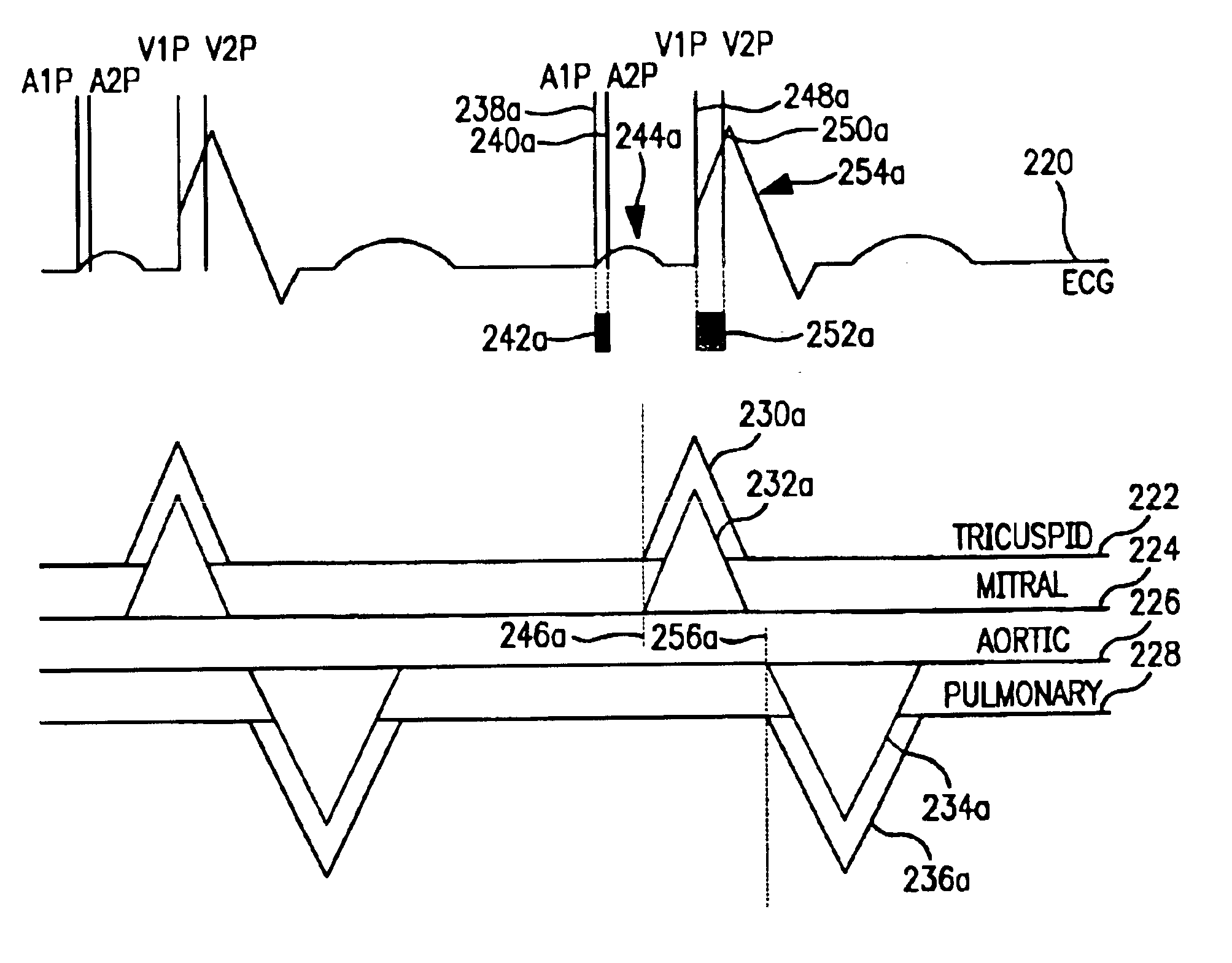
The lack of synchrony may be caused by factors such as differences in placement of stimulating electrodes proximate to the ventricles or the differences in the conductive pathways of the ventricles. The lack of synchrony may cause the ventricles to begin ejection of blood at different times. For some patients, asynchronous blood ejection is inefficient and undesirable. The techniques of the invention bring the ventricles into synchrony, resulting in improved hemodynamic performance.
The invention may offer one or more advantages. By selection of an interval that separates pacing pulses delivered to the ventricles or to the atria, the chambers of the heart may be synchronized for near-optimal cardiac performance. When the chambers are synchronized, the patient may experience improved cardiac performance, such as improved stroke volume and cardiac output. Moreover, the chambers of the heart may be resynchronized for near-optimal cardiac performance in response to changes in heart rate that may accompany changes in activity. In this manner, resynchronization can be achieved over a range of patient activity.

Problems solved by technology

These problems include, for example, an inability to adapt a pacing interval to current cardiac conditions to promote hemodynamic efficiency, and an inability to adapt a pacing interval to changing cardiac conditions.
The lack of synchrony may cause the ventricles to begin ejection of blood at different times. For some patients, asynchronous blood ejection is inefficient and undesirable.
Realization of synchrony at one heart rate, however, does not assure synchrony at another heart rate.
As a result of the change in heart rate, therefore, a pacing interval that produced synchrony at a lower heart rate may fail to produce synchrony at a higher heart rate.

Method used


Image

  • Cardiac resynchronization with adaptive A1-A2 and/or V1-V2 intervals
  • Cardiac resynchronization with adaptive A1-A2 and/or V1-V2 intervals
  • Cardiac resynchronization with adaptive A1-A2 and/or V1-V2 intervals

Examples


Embodiment Construction

In the following detailed description of the preferred embodiments, reference is made to the accompanying drawings that form a part hereof, and in which are shown by way of illustration specific embodiments in which the invention may be practiced. It is to be understood that other embodiments may be utilized and structural or logical changes may be made without departing from the scope of the present invention. The following detailed description, therefore, is not to be taken in a limiting sense, and the scope of the present invention is defined by the appended claims.

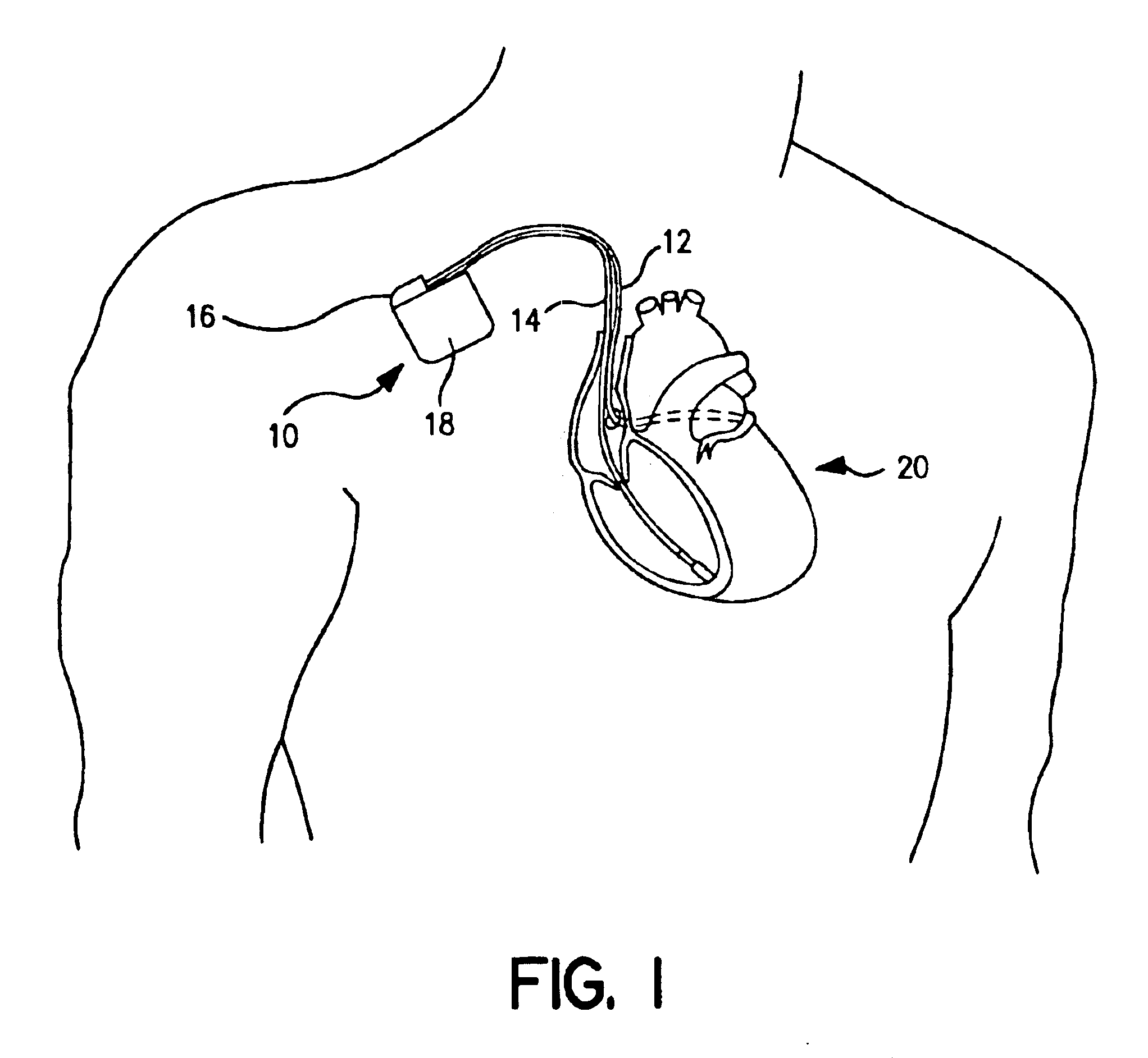
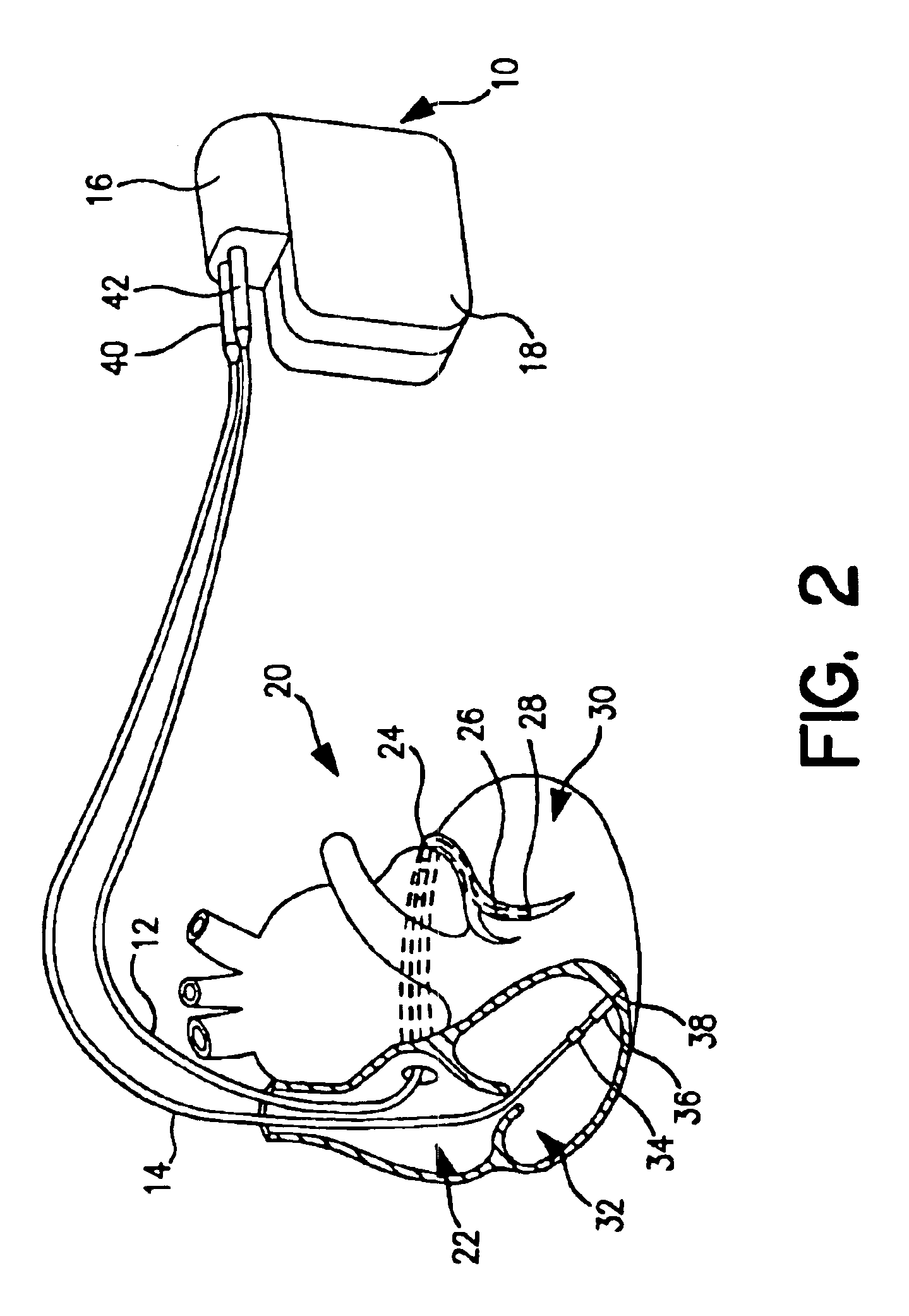
FIG. 1 is a simplified schematic view of pacemaker 10, which is one embodiment of an implantable medical device of the present invention. Pacemaker 10 shown in FIG. 1 comprises at least one of pacing and sensing leads 12 and 14 attached to connector module 16 of hermetically sealed housing 18 and implanted near human or mammalian heart 20. Pacing and sensing leads 12 and 14 sense electrical signals attendant to the dep...


PUM


Abstract

In a system that provides bi-atrial and / or bi-ventricular pacing, the system adjusts an interval between paces delivered to the atria, and / or an interval between paces delivered to the ventricles, as a function of heart rate. By adjusting the interval between paces as a function of heart rate, the atria and / or ventricles may be activated in a more synchronous and more hemodynamically efficient fashion.

Description

FIELD OF THE INVENTIONThe invention relates to cardiac pacing systems, and more particularly to multiple-chamber cardiac pacing systems.BACKGROUNDMany patients that suffer from congestive heart failure (CHF) develop a wide QRS complex resulting from a delayed activation of one of the ventricles in the heart, and inter- and / or intraventricular electrical-mechanical dysynchrony. This ventricular “dysynchrony” may be caused by dilation of the heart, which disrupts the conductive pathways and interferes with depolarization sequences. Ventricular dysynchrony may worsen heart failure symptoms.In a classic case of ventricular dysynchrony, the patient's right ventricle activates first, and the left ventricle activates at a later time. The patient often experiences a reduction in cardiac output because the ventricles begin contraction at slightly different times. The timing imbalance may also cause the patient to experience paradoxical septal motion, mitral regurgitation or decreased ventric...

Claims


Application Information

Patent Timeline
IPC IPC(8): A61N1/362A61N1/365A61N1/368
CPCA61N1/3627A61N1/3684A61N1/36542A61N1/36843
Inventor GRANDJEAN, PIERRE
Owner MEDTRONIC INC
Learn More