Method and apparatus for leak testing closed containers

Inactive Publication Date: 2005-01-11
WILCO AG
View PDF27 Cites 10 Cited by
  • Summary
  • Abstract
  • Description
  • Claims
  • Application Information

AI Technical Summary

Benefits of technology

Thereby, the present invention departs from the recognition that if a container to be tested is biased, leading to either compression or expansion of such container, biasing forces will apply to surfaces applied externally to the wall of the container as reaction forces of the expanded or the compressed container. Such reaction forces may easily be monitored. If

Problems solved by technology

If the container is leaky, there will occur an exchange of medium between the surrounding of

Method used


Image

  • Method and apparatus for leak testing closed containers
  • Method and apparatus for leak testing closed containers
  • Method and apparatus for leak testing closed containers

Examples


Embodiment Construction

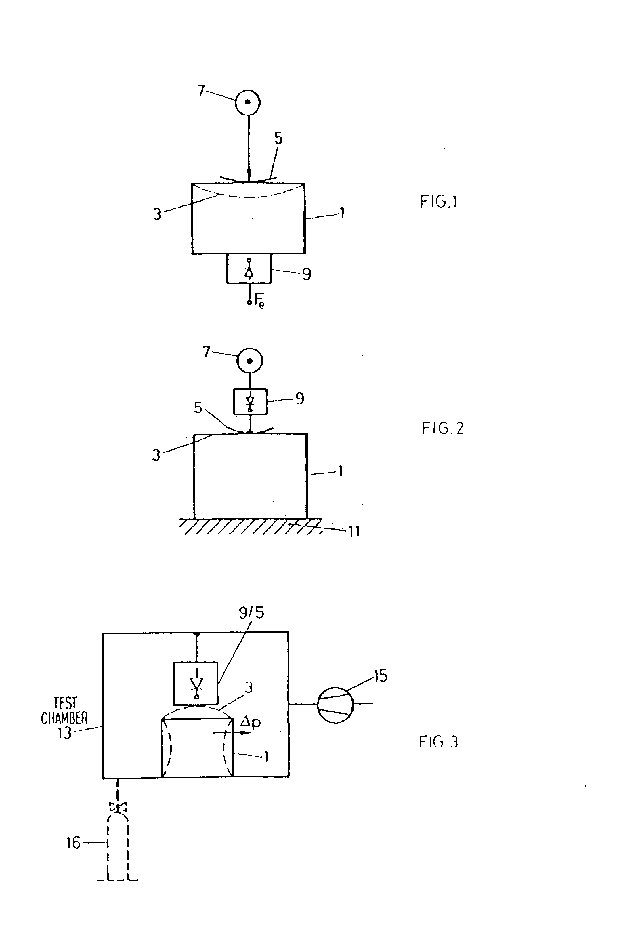
FIG. 1 shows schematically one principle according to the present invention. A container to be leak tested, 1, has an area of its wall 3 which is flexible. The principle of the present invention resides in the fact that for leak testing container 1 a biasing member 5 is moved by means of a drive 7 towards and onto the wall of the container 1 and a force detector 9 monitors the reaction force F and generates an electrical signal Fe1 according to that force F. As shown in FIG. 2 in a preferred mode the force detector 9 is directly coupled to the biasing member 5 and both are driven relative to and onto the flexible area 3 on the wail of the container 1, which latter resides, e.g., on a base plate 11.

In a still further preferred embodiment and as shown in FIG. 3 the drive 7, which moves one of the biasing member 5, of force detector 9 or of a combined force detector and biasing member 5 / 9 arrangement with respect to the flexible area 3 of the wall of container 1, is in fact realised as...


PUM


Abstract

Leak testing a closed container with at least one flexible wall area is performed with the method and apparatus wherein a biasing arrangement compresses or expands the container under test. A biasing force is monitored with a force detector applicable to the wall of the container. The force detector generates an electric output first biasing force signal at a first po9int in time which is stored for comparison with the monitored biasing force signal at a second subsequent point in time to generate a different signal as a leak indicative signal. A difference signal is generated at the first point in time from the first force measuring signal stored and the first force measuring signal. This latter difference signal is stored as a zero offset signal which is used to compensate zero offset of the generated difference signal.

Description

TECHNICAL FIELDThe present invention is directed to a method for leak testing closed containers with at least one flexible wall area and to leak testing apparatus for leak testing a closed container with such flexible wall area, irrespective whether such container is filled with a product or not.BACKGROUNDWhen testing closed containers one known technique is to arrange a container to be tested into a test cavity which is then sealingly closed, then to evacuate the interior space of the test cavity around the container to be tested and to evaluate the time behaviour of the pressure in the surrounding of the container after evacuation has been stopped at a predetermined level. Although this technique is of very high accuracy it necessitates utmost care for reaching such high accuracy. The volume of the test cavity and its shape must snugly fit the outside shape of the container to be tested. On one hand minimising this volume leads to respectively short evacuation time, on the other h...

Claims


Application Information

Patent Timeline
IPC IPC(8): G01M3/36G01M3/02
CPCG01M3/363
Inventor LEHMANN, MARTIN
Owner WILCO AG
Why Eureka
Try Eureka