Quick-detachable blade guard mounting structure

a blade guard and mounting structure technology, applied in the field of table saws, can solve the problem of taking a long time to mount/dismount the holder frame,

Inactive Publication Date: 2005-01-11
DURQ MACHINERY
View PDF12 Cites 155 Cited by
  • Summary
  • Abstract
  • Description
  • Claims
  • Application Information

AI Technical Summary

Benefits of technology

The present invention has been accomplished under the circumstances in view. It is therefore the main object of the present invention to provide a quick-detachable blade guard mounting structure, which enables the user to mount / dismount the saw blade guard quickly without the use of any tools.

Problems solved by technology

Therefore, it takes much time to mount / dismount the holder frame 3.

Method used


Image

  • Quick-detachable blade guard mounting structure
  • Quick-detachable blade guard mounting structure
  • Quick-detachable blade guard mounting structure

Examples


Embodiment Construction

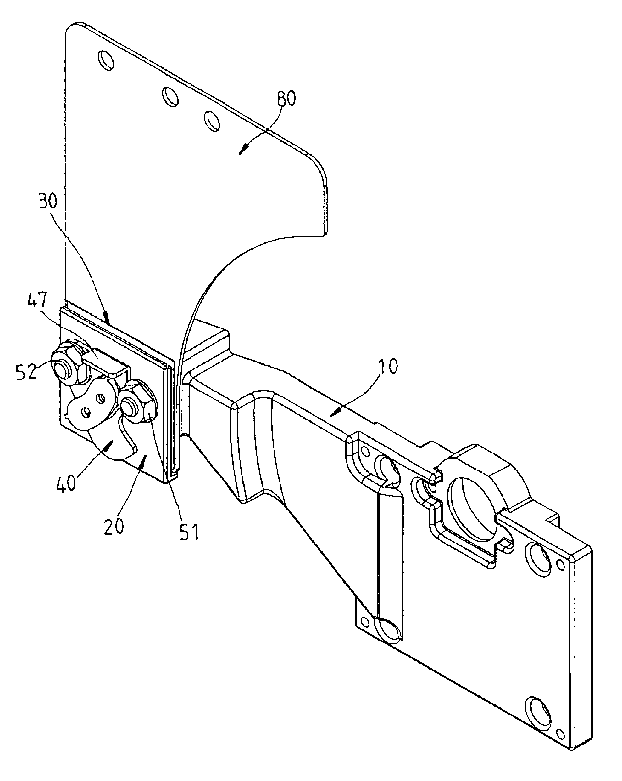
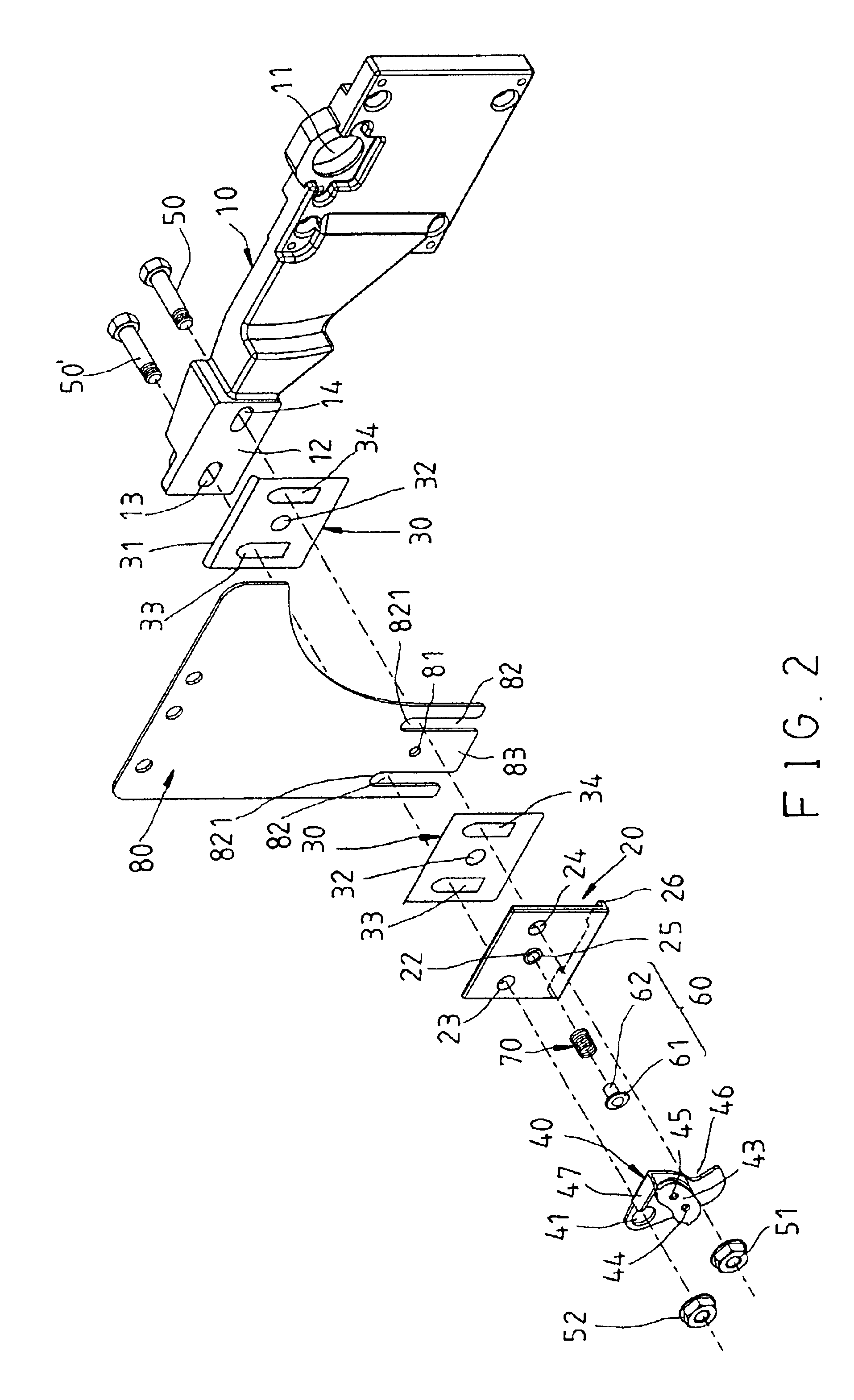
Referring to FIGS. from 2 through 6, a quick-detachable blade guard mounting structure is a part of a table saw, comprising mounting frame 10, a holding down member 20, two cushions 30, a lever 40, two screw rods 50;50′, a locking member 60, a spring member 70, and a blade guard holder member 80.

The mounting frame 10 is mounted in the bottom side of the table of the table saw, having a pivot hole 11 in one side thereof for the mounting of a saw blade. The mounting frame 10 can be adjusted upwards to hold the saw blade in the cutting position partially above the top side of the table of the table saw, or downwards to hold the saw blade in the received position below the table of the table saw. The mounting frame 10 further comprises a vertical wall 12 extended from one side thereof remote from the pivot hole 11, and two through holes 13;14 horizontally extended through the vertical wall 12.

The holding down member 20 is a plate member of certain thickness vertically disposed at an out...


PUM

PropertyMeasurementUnit
timeaaaaaaaaaa
thicknessaaaaaaaaaa
thin thicknessaaaaaaaaaa

Abstract

A quick-detachable blade guard mounting structure. The structure includes a mounting frame, a holding down member defining with one side of the mounting frame, a gap, a blade guard holder member insertable into the gap, a stop device adapted for stopping the blade guard holder member in the gap, a lever pivoted to the holding down member and adapted for moving between a first position to unlock the blade guard holder member and a second position to lock the blade guard holder member.

Description

BACKGROUND OF THE INVENTION1. Field of the InventionThe present invention relates to a table saw and, more specifically, to a quick-detachable blade guard mounting structure for table saw.2. Description of the Related ArtA table saw is provided with a movable saw blade guard adapted for protecting the saw blade when not in operation. During the operation of the table saw, the saw blade guard is lifted and placed at one side. When the table saw turned off, the saw blade guard is closed to mask the saw blade.FIG. 1 illustrates a table saw constructed according to the prior art. According to this design, the worktable 1 has an elongated slot through which the saw blade 2 protrudes over the top side of the worktable 1. A holder frame 3 is provided at one end of the elongated slot. A blade guard 4 is pivoted to the holder frame 3 and adapted for protecting the saw blade 2. The holder frame 3 has two longitudinal coupling slots 5 coupled to respective screw rods (not shown) at the bottom ...

Claims


Application Information

Patent Timeline
Patent Type & Authority Patents(United States)
IPC IPC(8): B27G19/00B27G19/02
CPCB27G19/08B27G19/02Y10T83/773Y10T83/7734Y10T83/732Y10T83/738Y10T83/2077
Inventor HUANG, PETER
Owner DURQ MACHINERY
Why Eureka
Try Eureka