Elevator safety arrangement having safety spaces

a safety space and elevator technology, applied in the direction of elevators, building lifts, transportation and packaging, etc., can solve the problems of difficult alternative consideration, inability to extend the shaft upwards or downwards in most cases in construction technology or at least too expensive, and difficulty in determining the alternative, so as to reduce the number of short-duration breaks and reduce the number of malfunctions of the elevator system , the effect of improving the reliability and utilization rate of the elevator system

Active Publication Date: 2011-02-22
KONE CORP
View PDF14 Cites 44 Cited by
  • Summary
  • Abstract
  • Description
  • Claims
  • Application Information

AI Technical Summary

Benefits of technology

[0047]In the safety arrangement of the invention, as the states of the detectors in the electric safety system are monitored by a separate electric safety controller, the signals to be monitored can be filtered by software in the electric safety controller as necessary. Thus, the system is immune to short-duration breaks in the contacts of the switches. As the number of malfunctions of the elevator system caused by these short-duration breaks is reduced, the reliability and utilization rate of the elevator system are improved.
[0049]The electric safety system of the invention contains separate end limit markers for normal and maintenance operation. The fact that, in the solution of the invention, both the choice as to which end limit switches are to be used in each situation and the deduction regarding the operating state of the safety arrangement are performed in a centralized manner by the electric safety controller ensures that the operating state of the safety arrangement determined by measurements by the detectors of the electric safety system corresponds to the end limit markers being used. When the end limit markers are read by the electric safety controller by means of end limit marker readers, it is possible to make sure that the correct end limit markers are selected in a situation where a serviceman operates the elevator in maintenance mode from the elevator shaft. By fitting the end limit markers and marker readers advantageously in a mutually staggered manner, it will be sufficient to use only two end-limit marker readers. This simplifies the safety arrangement, reduces the wiring and improves the reliability of the system. Using the electric safety controller, it is also possible to permit a direction-dependent read logic in the reading of end-limit markers. If for example
[0050]As the switches comprised in the elevator safety arrangement are read in the manner proposed in the invention by measuring the current flowing through the resistors fitted in connection with the switches, the state of the series-connected switches can be determined by the electric safety controller via a single current measurement. This simplifies the connection interface between the electric safety controller and the switches to be read. In the safety regulations concerning the elevator industry it is stated that, when metal film resistors are preferably used as components in an electric safety circuit, a short circuit of resistors can be disregarded in the consideration of failures. When a resistor undergoes a failure by being broken, the failure can always be detected by the electric safety controller, and therefore resistors can also be used to measure safety circuits, such as in the case of landing door switches. Resistors are also advantageous as components for use in the measurements in the electric safety system.
[0054]As the number of discrete components, such as relays, in the electric safety system is reduced, this also reduces the problems caused by mechanical wear which are inherent with these components and restrict their service life.

Problems solved by technology

When elevators in old buildings are to be modernized, problems are often encountered because the safety regulations have been changed in the course of years and the spaces above and below the elevator car in the elevator shaft are not large enough to satisfy the new safety regulations.
Extending the shaft upwards or downwards is in most cases impossible in respect of construction technology or at least too expensive and difficult to be considered as an alternative.
In this case, there is no sufficient safety space left in the elevator shaft above and below the elevator car to provide personal protection for a serviceman working on the top of the elevator car or in the elevator shaft.
The solution for an electric safety arrangement described in this specification is based on discrete components, such as relays and switches, and is therefore very complicated in respect of the required wiring.
Moreover, the testing of operation, which is important in regard of safety of operation of the switch, requires a separate control logic and thus further increases the complexity of the solution.
As the electric safety arrangement is implemented using discrete components, such as relays and switches, the system is sensitive to momentary breaks in the control of the switches and to contact problems, which occur in an elevator system from time to time.
If the operation of the elevator system is interrupted due to momentary breaks like this, then the reliability of operation of the elevator system also deteriorates.
However, the safety controller according to this specification can not in itself provide a level of safety sufficient for the operation of the safety arrangement according to the present invention.

Method used


Image

  • Elevator safety arrangement having safety spaces
  • Elevator safety arrangement having safety spaces
  • Elevator safety arrangement having safety spaces

Examples


Embodiment Construction

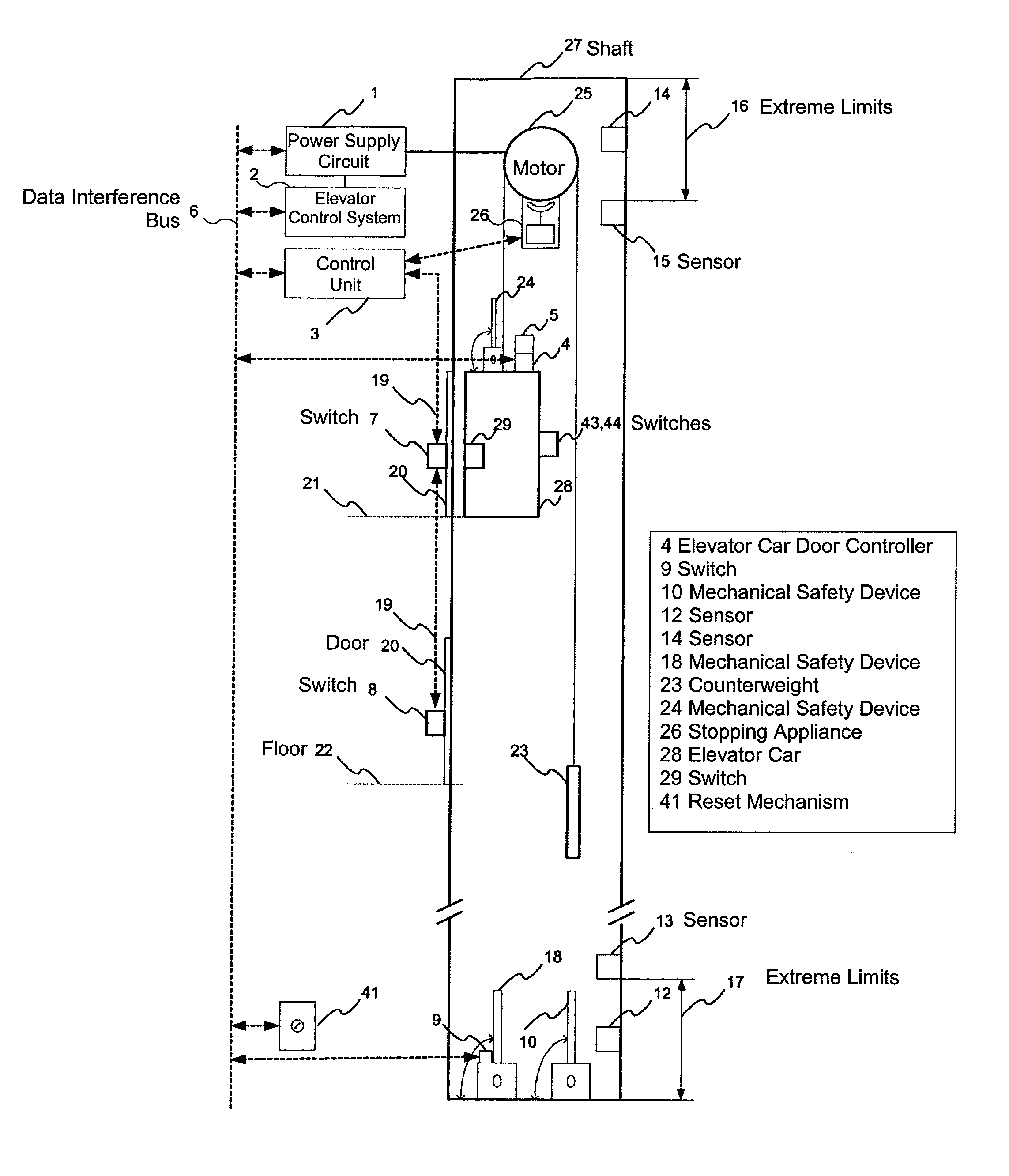
[0059]FIG. 1 represents an elevator system applying a safety arrangement according to the invention. An elevator car 28 has been fitted to travel in an elevator shaft 27 from floor to floor 21, 22. This elevator system according to the invention also comprises a counterweight 23, but the elevator system of the invention may also be implemented without a counter-weight. The elevator motor 25 is disposed in the elevator shaft, but it may also be placed in a machine room.

[0060]The extreme limits of movement of the elevator car in the elevator shaft are determined by end limit markers 12, 13, 14, 15. During normal operation, the elevator car travels between the extreme limits determined by end limit markers 12, 14. When the mechanical safety devices 10, 18, 24 have been set into their active position, the elevator can only be operated in maintenance mode within the shaft portion defined by end limit markers 13, 15. Fitted in conjunction with the elevator car are end limit marker readers...


PUM


Abstract

An elevator safety arrangement and a method for implementing safety spaces in an elevator has a mechanical safety device which can be set to a working position to ensure a sufficient safety space in the elevator shaft and an electric safety system for identifying the operating state of the mechanical safety device. According to the method of the invention, detectors in the electric safety system are read by an electric safety controller and, when a functional deviation is detected, one or more stopping devices are actuated to bring the elevator system into a safe operating state.

Description

[0001]This application is a Continuation of PCT / FI2007 / 000302 filed on Dec. 21, 2007, and claims priority under 35 U.S.C. §119(a) on Patent Application No. 20070006 filed in Finland on Jan. 3, 2007, respectively, all of which are hereby expressly incorporated by reference into the present application.FIELD OF THE INVENTION[0002]The present invention relates to an elevator safety.PRIOR ART[0003]When elevators in old buildings are to be modernized, problems are often encountered because the safety regulations have been changed in the course of years and the spaces above and below the elevator car in the elevator shaft are not large enough to satisfy the new safety regulations. Extending the shaft upwards or downwards is in most cases impossible in respect of construction technology or at least too expensive and difficult to be considered as an alternative.[0004]New buildings are constructed with a view to saving space in the elevator shaft. This is accomplished by designing the spaces...

Claims


Application Information

Patent Timeline
Patent Type & Authority Patents(United States)
IPC IPC(8): B66B1/34
CPCB66B5/0056B66B13/22B66B5/0062
Inventor KATTAINEN, ARIHEIKKILA, KIMMOSYRMAN, TIMO
Owner KONE CORP
Why Eureka
Try Eureka