Light source apparatus for electronic endoscope and electronic endoscope having the light source apparatus

a technology of light source apparatus and electronic endoscope, which is applied in the direction of printers, instruments, etc., can solve the problems of troublesome manufacturing process, high manufacturing cost, and complex structure of rotary shutters

Inactive Publication Date: 2008-09-02
HOYA CORP
View PDF8 Cites 48 Cited by
  • Summary
  • Abstract
  • Description
  • Claims
  • Application Information

AI Technical Summary

Benefits of technology

[0006]The present invention provides a light source apparatus for an electronic endoscope in which the range of relative rotation angle between the pair of aperture controlling rotary plates can be easily limited to a predetermined rotation angle range and rotations of the pair of aperture controlling rotary plates can be easily controlled. The present invention further provides an endoscope having such a light source apparatus.
[0007]Moreover, the present invention provides a light source apparatus for an electronic endoscope, wherein the pair of aperture controlling rotary plates can easily be assembled in a manner to be arranged coaxial with each other, and further provides an electronic endoscope having such a light source apparatus.

Problems solved by technology

In Japanese Unexamined Patent Publication No. 62-69222, light modulation can be performed, however, the structure of the rotary shutter is complex.
Accordingly, the manufacturing cost is high and the manufacturing process is troublesome.
Moreover, in order to achieve such a construction, the outer diameter of the rotary shutter must be several times larger than that of the light bundle, thus resulting in an increase in size of the rotary shutter.
If the rotary shutter is asymmetrical in shape with respect to the rotation axis thereof in order to vary the aperture, the center of rotation does not align with the center of gravity, so that the rotary shutter tends to lose balance during rotation.
Consequently, correct emission of the illuminating light cannot occur, and the rotary shutter and the surrounding members may break.

Method used


Image

  • Light source apparatus for electronic endoscope and electronic endoscope having the light source apparatus
  • Light source apparatus for electronic endoscope and electronic endoscope having the light source apparatus
  • Light source apparatus for electronic endoscope and electronic endoscope having the light source apparatus

Examples


first embodiment

[0046]a light source apparatus according to the present invention will be discussed below with reference to FIGS. 1 through 10.

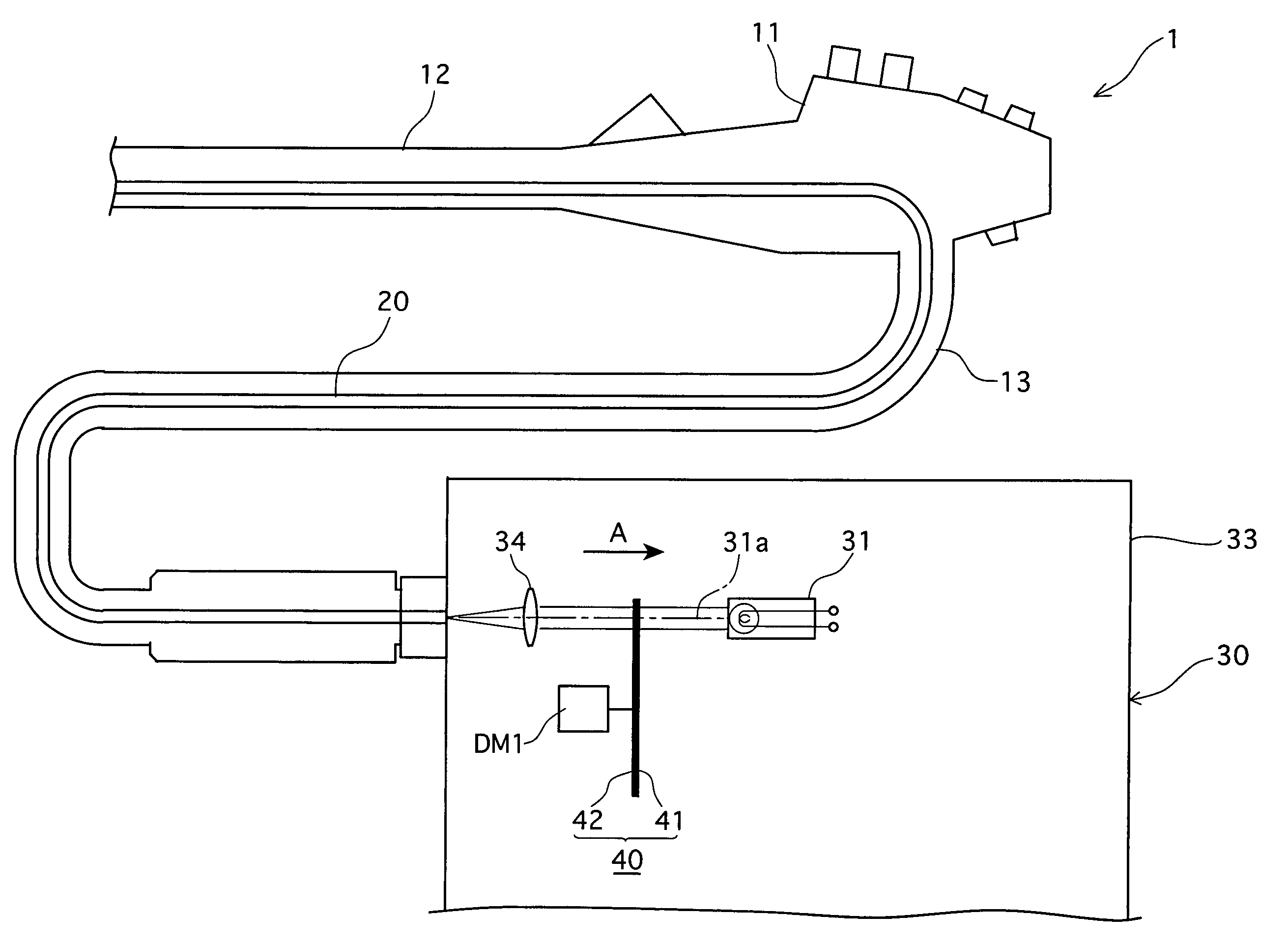
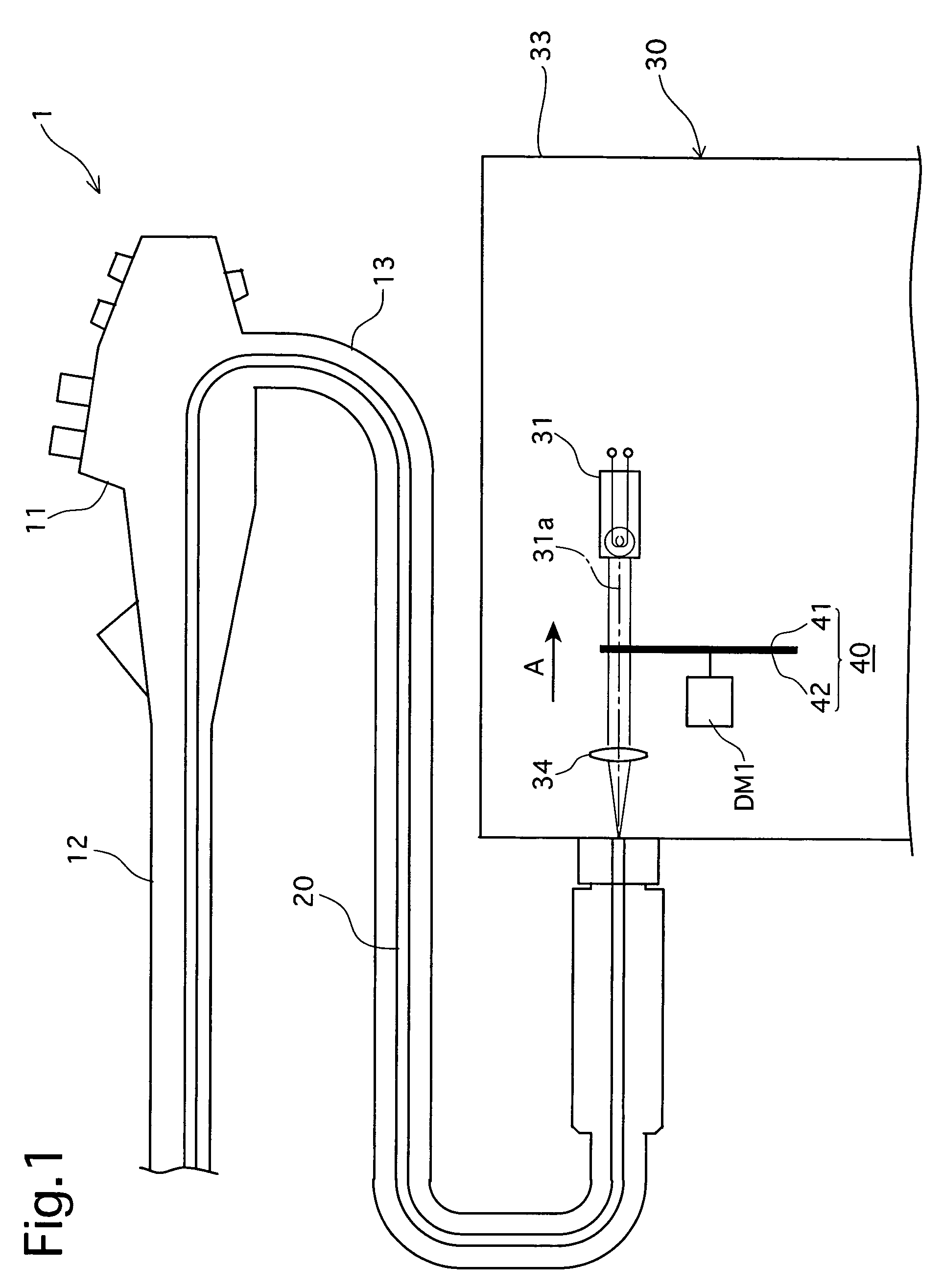
[0047]As shown in FIG. 1, an electronic endoscope 1 includes an operating portion 11 which is held by an operator, a flexible and elongated insertion portion 12 extending from the operating portion 11, and a connecting tube 13 extending from the operating portion 11. A light guide (light guide fiber bundle) 20 is arranged in the operating portion 11, the insertion portion 12, and the connecting tube 13 to emit illuminating light out of an emitting end surface formed at the distal end of the endoscope 1.

[0048]The electronic endoscope 1 is connected to a light source apparatus 30 through the connecting tube 13. The light source apparatus 30 is provided in a casing 33 thereof with a lamp (light source) 31. Light (illuminating light) emitted from the lamp 31 is incident upon the light guide 20 at the incident end surface thereof. The light transmitted through th...

second embodiment

[0085]the light source apparatus according to the present invention will be hereinafter discussed with reference mainly to FIGS. 11 through 13.

[0086]The second embodiment of the light source apparatus is different from the first embodiment of the light source apparatus only in the drive mechanism DM2, and accordingly, the elements corresponding to those in the first embodiment are designated by like reference numerals and no detailed explanation thereof will be given below.

[0087]A stationary bearing (gear bearing) AS secured to the casing 33 of the light source apparatus 30 is provided around the drive shaft 50 and the drive shaft of the chopper motor M1. The stationary bearing AS is in the form of a cylinder having open ends and is positioned to be coaxial with the drive shaft 50 and the drive shaft of the chopper motor M1. The second embodiment of the light source apparatus is provided, instead of the internal tooth gear 51 and the internal / external tooth gear 68 in the first embo...

third embodiment

[0098]The drive mechanism DM3 in the light source apparatus is constructed as follows.

[0099]A drive shaft (rotating shaft) 190 is fixed to the first aperture controlling rotary plate 41 at the center thereof to extend perpendicular to the first aperture controlling rotary plate 41 (parallel with the light axis 31a). The drive shaft 190 is rotated on the axis thereof by the chopper motor M1 that is secured to the casing 33 of the light source apparatus 30. The first aperture controlling rotary plate 41 is provided, on its surface opposed to the second aperture controlling rotary plate 42 (opposite to the drive shaft 190), with a first internal / external tooth gear (first internal tooth gear) 191, which is substantially in the form of a cylinder coaxial with the drive shaft 190. An end surface of the first internal tooth gear 191 on the second aperture controlling rotary plate 42 side is provided with a circular opening coaxial with the drive shaft 190. An internal tooth gear 192 ident...


PUM


Abstract

A light source apparatus for an electronic endoscope includes a light source; a rotary shutter including a pair of coaxial aperture controlling rotary plates, which are selectively rotatable relative to and together with each other and each includes light interception portions and opening portions, wherein a combined opening angle of the opening portions is varied by a relative rotation of the aperture controlling rotary plates, and the amount of emitted light is controlled by varying the combined opening angle, and the controlled amount of the light is emitted through the rotary shutter by integral rotation of the aperture controlling rotary plates; and a mechanical stop device, positioned between the aperture controlling rotary plates, for limiting the range of relative rotation angle between the aperture controlling rotary plates from a maximum opening angle to a minimum opening angle.

Description

BACKGROUND OF THE INVENTION[0001]1. Field of the Invention[0002]The present invention relates to an electronic endoscope, and more specifically relates to a light source apparatus for an electronic endoscope using a plurality of aperture controlling rotary plates.[0003]2. Description of the Prior Art[0004]In conventional electronic endoscopes, in order to provide appropriate light modulation, an endoscope recording apparatus has been proposed in, for example, Japanese Unexamined Patent Publication No. 62-69222. The apparatus disclosed in this publication is provided with a rotary shutter having a rotatable shaft, wherein the distance between the axis of the rotatable shaft and the optical axis of illuminating light emitted from a light source for the endoscope is variable. The rotary shutter is shaped so that a difference in peripheral speed occurs between the radial portions thereof, i.e., the rotary shutter is shaped so that the aperture size varies during rotation of the rotary s...

Claims


Application Information

Patent Timeline
Patent Type & Authority Patents(United States)
IPC IPC(8): F16H3/72
CPCG03B29/00
Inventor ITO, SHUNICHI
Owner HOYA CORP
Why Eureka
Try Eureka