Cover assembly for a concealed sprinkler head

a technology of cover assembly and sprinkler head, which is applied in fire rescue and other directions, can solve the problems of inconvenient maintenance of the cover, and achieve the effect of increasing the rigidity

Inactive Publication Date: 2005-01-11
SENJU SPRINKLER
View PDF10 Cites 81 Cited by
  • Summary
  • Abstract
  • Description
  • Claims
  • Application Information

AI Technical Summary

Benefits of technology

The cover plate may partly or wholly be made of a shape-memory alloy so that its peripheral edge may be bent in a downward direction when the ambient tem

Problems solved by technology

One problem arises with this arrangement.
How

Method used


Image

  • Cover assembly for a concealed sprinkler head
  • Cover assembly for a concealed sprinkler head
  • Cover assembly for a concealed sprinkler head

Examples


Embodiment Construction

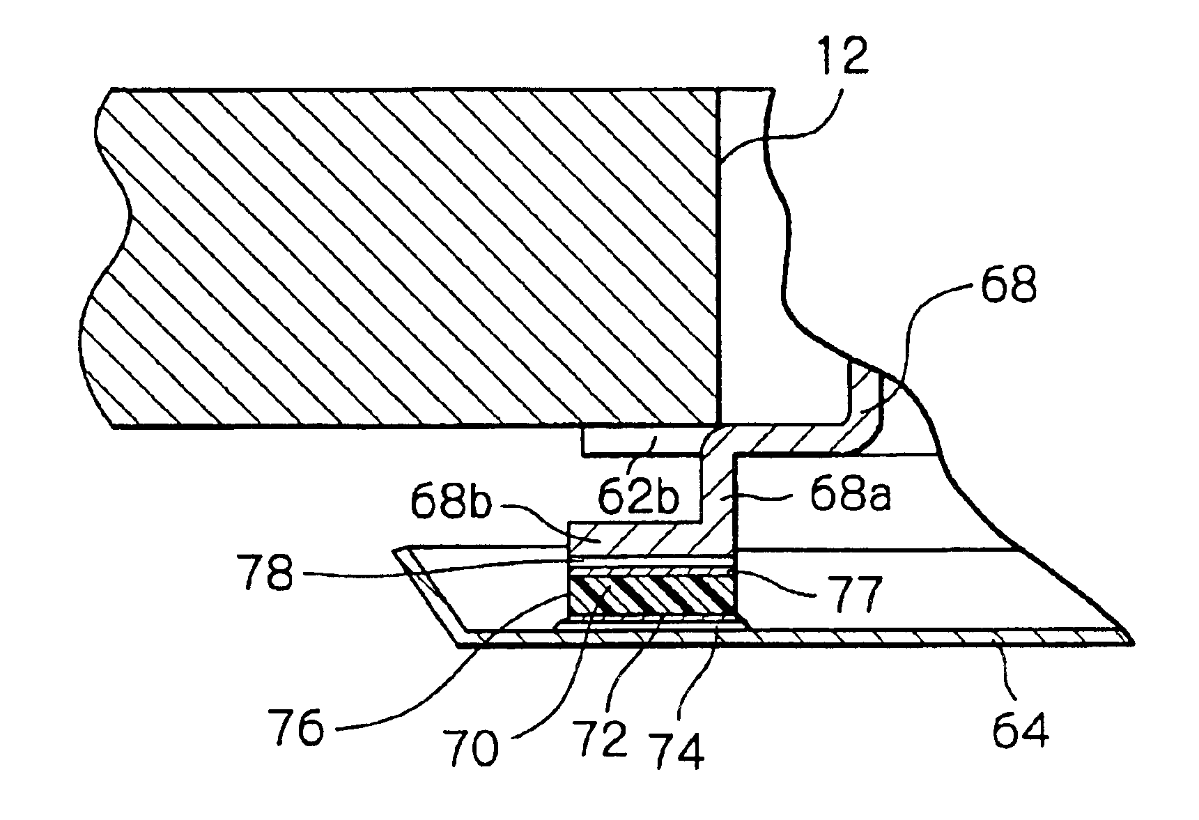
Referring now to FIG. 1, there is illustrated a concealed sprinkler head, generally designated by the reference numeral 10, mounted in a hole 12 in the ceiling of a room such that the bottom of the sprinkler head is substantially flush with the ceiling.

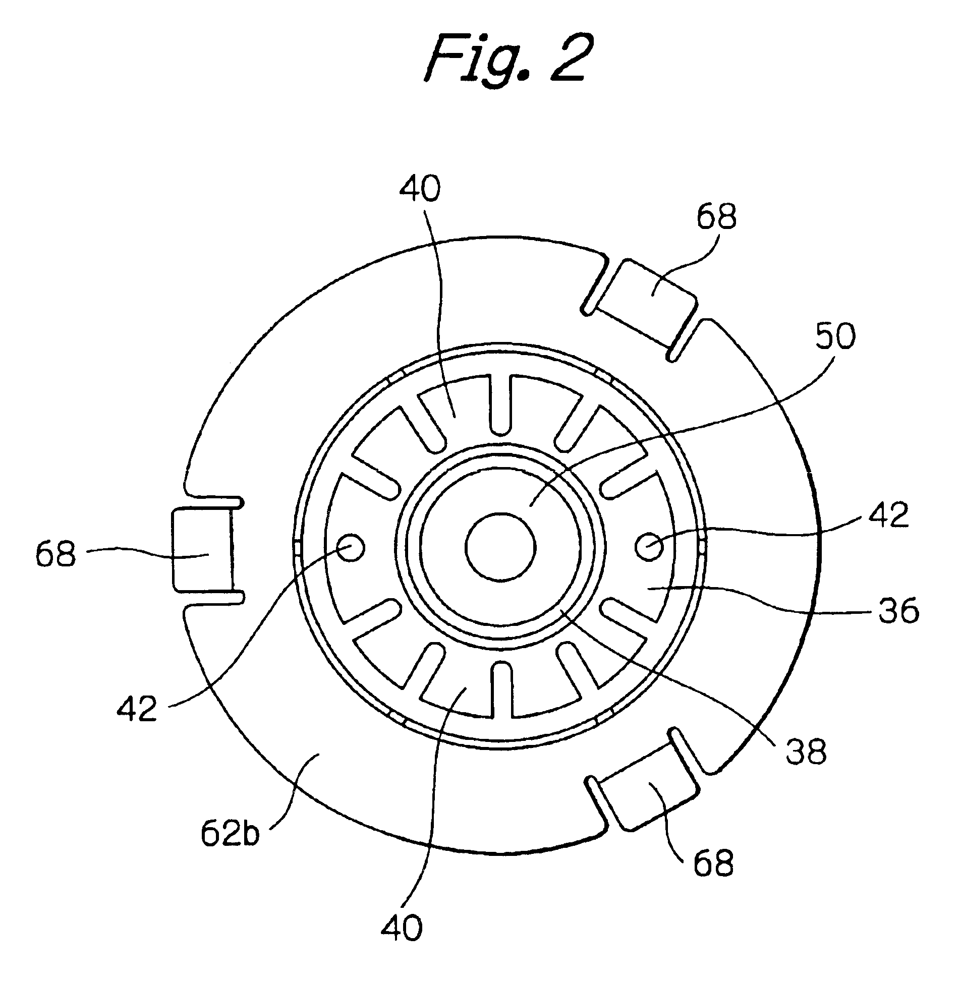
In the illustrated embodiment, the sprinkler head 10 includes a vertically extending tubular body 14 with a threaded upper or inlet end 14a adapted to be connected to a water line 16, and a lower or outlet end 14b. The water line 16 is communicated with a supply of pressurized water or other fire extinguishing fluid (not shown). An internal passage 14c is defined in the tubular body 14 and extends between the inlet end 14a and the outlet end 14b. An annular flange 18 extends around the outer periphery of the tubular body 14 and is located midway between the inlet end 14a and the outlet end 14b. A generally cylindrical housing 20 depends from the annular flange 18. A generally cylindrical casing 22 is secured around the lower end of th...


PUM


Abstract

A concealed sprinkler head is mounted above the ceiling of a fire protected zone. The sprinkler head includes a housing within which a valve and other operative parts are contained. A decorative cover plate is secured to the housing to conceal the sprinkler head within the ceiling so that none of the operative parts is visible. The cover assembly includes a thin metallic cover plate made of a heat conductive material such as copper, and a metallic skirt including a cylindrical wall threaded on the housing, an annular flange extending outwardly from one end of the cylindrical wall, and a plurality of tabs extending downwardly from the flange. A plurality of heat insulative elements are disposed between the tabs and the cover plate. A metallic layer is attached to the lower surface of each of the insulative elements. A layer of fusible material is disposed between the metallic layer and the cover plate to secure each of the insulative elements to the cover plate through the metallic layer.

Description

BACKGROUND OF THE INVENTIONThe present invention relates generally to automatic sprinkler heads and more particularly, to a decorative cover assembly adapted to conceal a pendent sprinkler head within the ceiling of a fire protected enclosure.Sprinkler systems are used extensively to provide automatic fire protection for residential, commercial and public buildings. There are two types of pendent sprinkler heads for ceiling applications, one referred to by the term “concealed” and the other referred to by the term “flush”. A concealed sprinkler head has its entire body located above the lower surface of the ceiling of an enclosure in which it is installed. A flush sprinkler head has the majority of its body located above the lower surface of the ceiling, but a thermally responsive element and its related elements are partly or wholly located below the ceiling. Thus, the concealed sprinkler head is less obstructive and more aesthetical than the flush sprinkler head.U.S. Pat. No. 4,01...

Claims


Application Information

Patent Timeline
IPC IPC(8): A62C37/08A62C37/09A62C37/11
CPCA62C37/09
Inventor KIKUCHI, TETSUROISHIKAWA, HIROKIKOIWA, YASUAKI
Owner SENJU SPRINKLER
Why Eureka
Try Eureka