Medical puncturing device

Inactive Publication Date: 2005-01-11
UNOMEDICAL AS
View PDF25 Cites 181 Cited by
  • Summary
  • Abstract
  • Description
  • Claims
  • Application Information

AI Technical Summary

Benefits of technology

By these features a simple construction is obtained which provides a reliable function as t

Problems solved by technology

The use of a medical puncturing device comprising a rigid needle may lead to some disadvantages during use of such device, viz, the potential danger of unintended exposure to the needle tip after the needle has been discarded.
Although these

Method used


Image

  • Medical puncturing device
  • Medical puncturing device
  • Medical puncturing device

Examples


Embodiment Construction

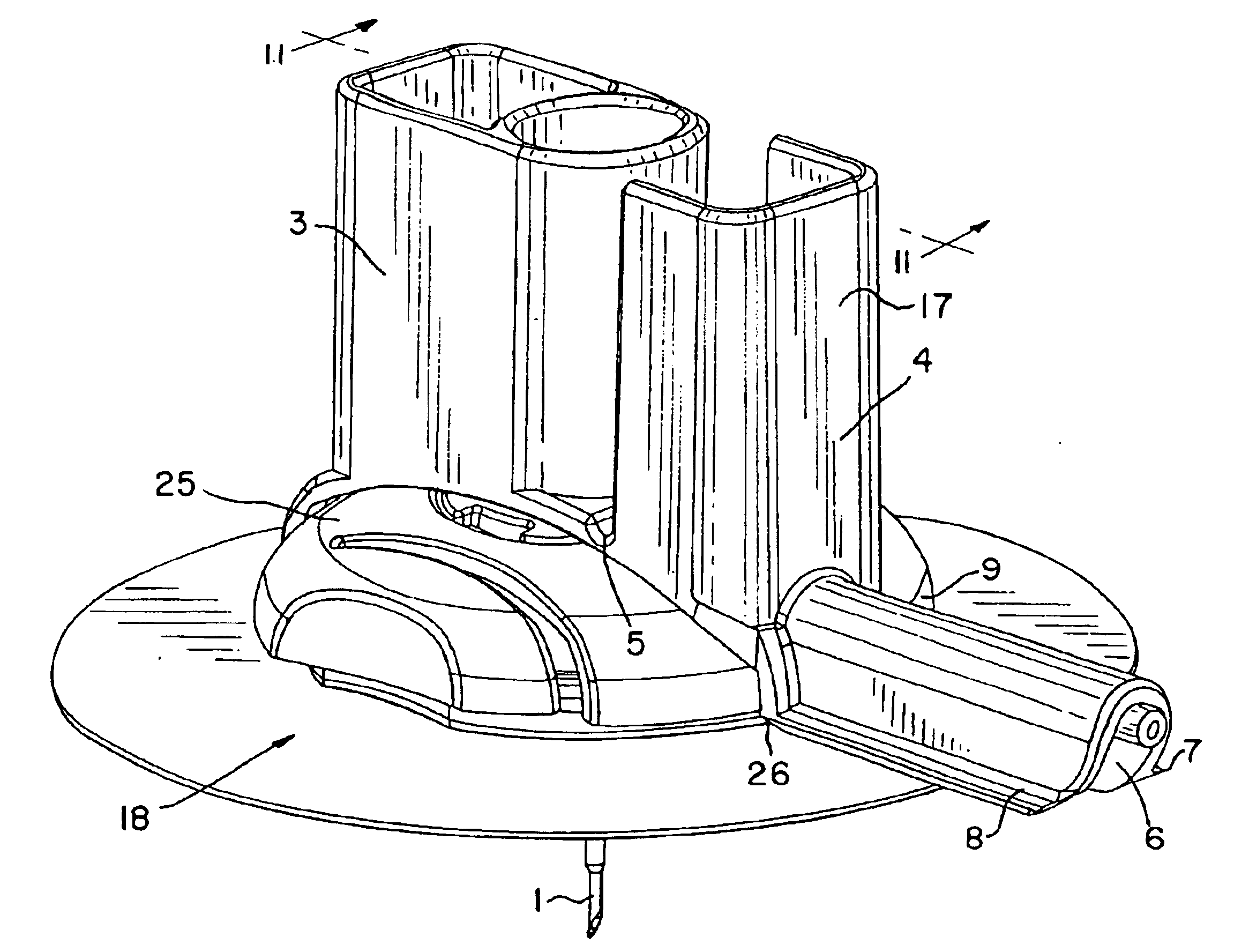
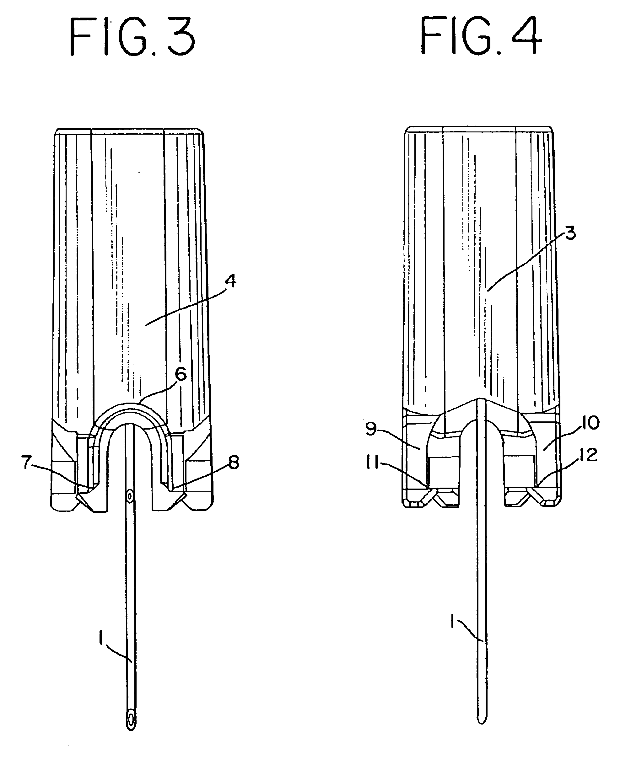
From FIG. 1 a preferred embodiment of the medical puncturing device appears. The device comprises a rigid needle 1 mounted in a needle hub 2. The needle is at the end opposite the needle hub 2 pointed or tapered so as to facilitate puncturing e.g. by the insertion of a soft cannula. The needle hub comprises a handle part 3, which is at one side connected to a shield part 4 via a hinge 5 formed as a material area with a reduced thickness. The shield part 4 has the shape of a half tube 6 having at the edges at both sides flanges 7, 8. The shield part 4 comprises a pivoting handle 17. At the opposite side of the needle hub 2 in relation to the needle connection point the needle hub 2 comprises two arms 9, 10 having barbs 11,12 at their opposed sides 15,16.

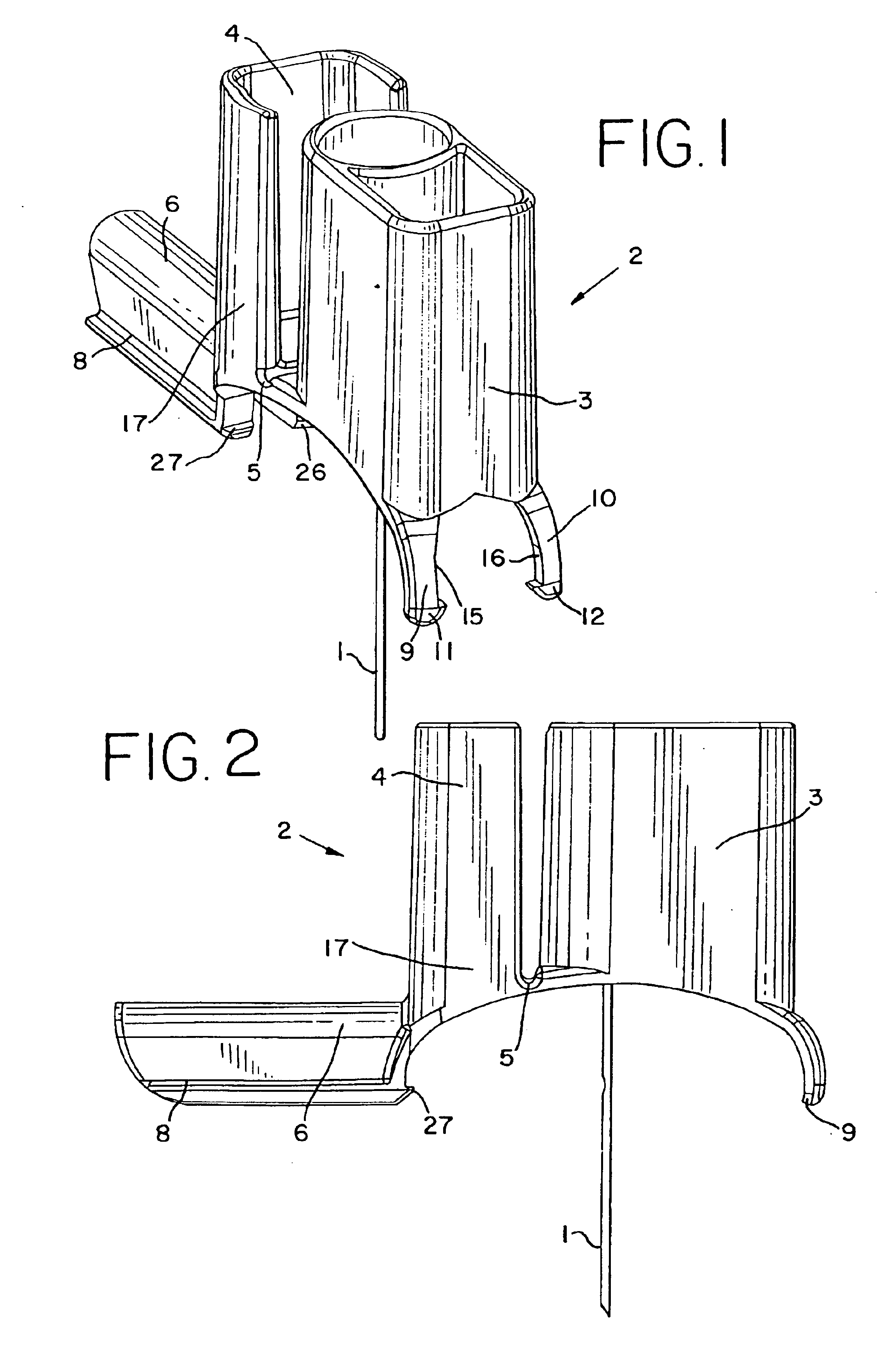
From FIG. 2 the puncturing device appears in a side view more clearly showing the transition area 5 where the shield part 4 is pivoted in relation to the handle part 3 by a pivoting action on the pivoting handle 17 by one hand while h...


PUM


Abstract

The invention relates to a medical puncturing device comprising a rigid needle being at one end adapted for facilitating the puncturing and comprising at the opposite end a hub, the hub comprising a handle part and a shield part being pivotable in relation to the handle part and further comprising locking means on the shield part and the handle part, the locking means being adapter to interlock the shield and the handle part in a pivoted position of the shield part where the rigid needle is covered by this.

Description

BACKGROUND OF THE INVENTIONThe present invention relates to a medical puncturing device e.g. for use in connection with the insertion of a soft cannula where the soft cannula e.g. forms part of a infusion device for subcutaneous delivery of a medication or a therapeutic fluid by means of an external infusion system and more particularly to a medical puncturing device capable of being discarded without the danger of causing unintended harmful injuries to persons afterwards.The medical puncturing device will in the following be explained in connection with the field of subcutaneous infusion devices. Such infusion devices are generally known in the art for delivering a medication or a therapeutic fluid to a subcutaneous site in a patient. Such devices commonly comprise a soft tubular cannula extending from a housing adapted to receive the desired medication via means, e.g. disconnectable means, for suitable connection to further components of the infusion system. The possibility of dis...

Claims


Application Information

Patent Timeline
IPC IPC(8): A61M25/06A61M5/158A61M5/14A61M5/32
CPCA61M25/0631A61M5/3216Y10S128/919A61M2005/1585A61M2005/1581
Inventor NIELSEN, JAN WILLUMLARSEN, BJ.O SLASHED.RN GULLAKMATHIASEN, ORLADELZAC, MARCTEISEN-SIMONY, CLAUDE
Owner UNOMEDICAL AS
Why Eureka
Try Eureka