Magnetoinductive flowmeter

a flowmeter and magnetic field technology, applied in the direction of electromagnetic flowmeters, volume/mass flow, instruments, etc., can solve the problems of affecting the signal-to-noise ratio, which is detrimental to the signal-to-noise ratio, and still contains a significant noise component of the voltage signal collected at the sampling electrod

Inactive Publication Date: 2005-01-18
AGRI GENETICS +1
View PDF7 Cites 5 Cited by
  • Summary
  • Abstract
  • Description
  • Claims
  • Application Information

AI Technical Summary

Benefits of technology

It is therefore the objective of this invention to introduce a magnetoinductive flowmeter that displays a good ...

Problems solved by technology

These solutions according to WO 85/04954 and other prior-art notwithstanding, a voltage signal collected at the sampling electrode will still contain a significant noise component especially when there is a substantial proportion of solid particles such as sand, etc. in the flowing medium.
Howev...

Method used


Image

  • Magnetoinductive flowmeter
  • Magnetoinductive flowmeter
  • Magnetoinductive flowmeter

Examples


Embodiment Construction

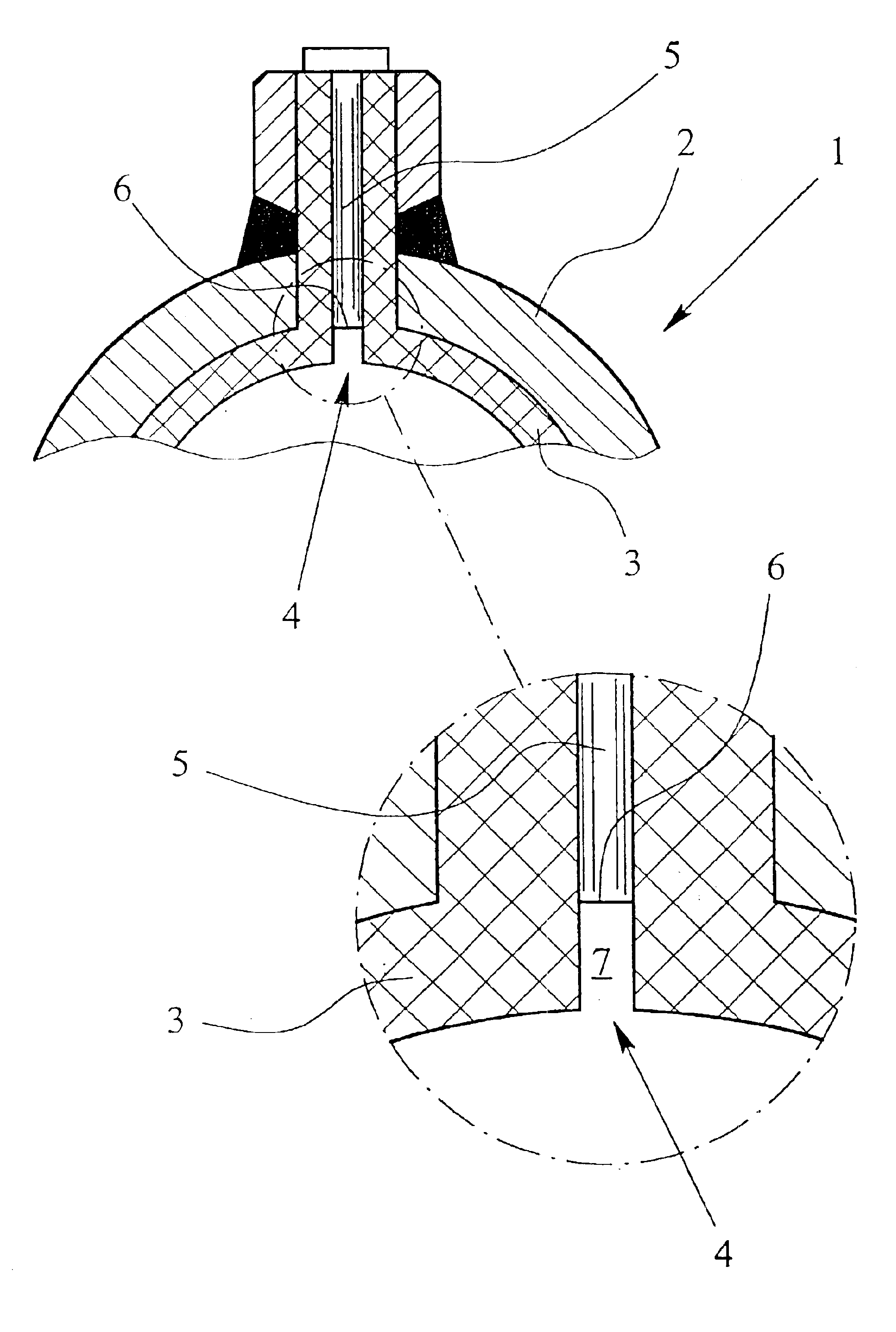
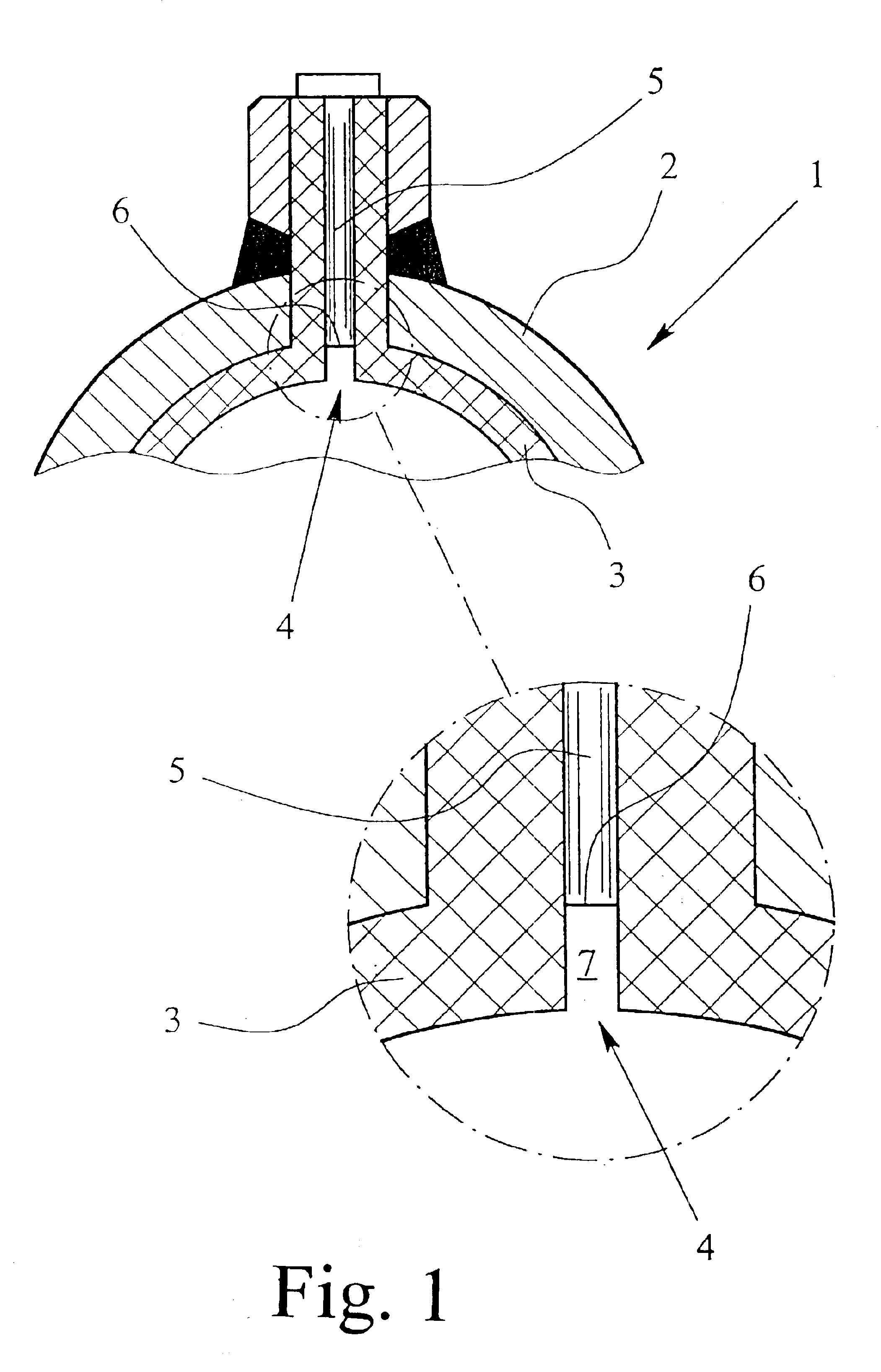
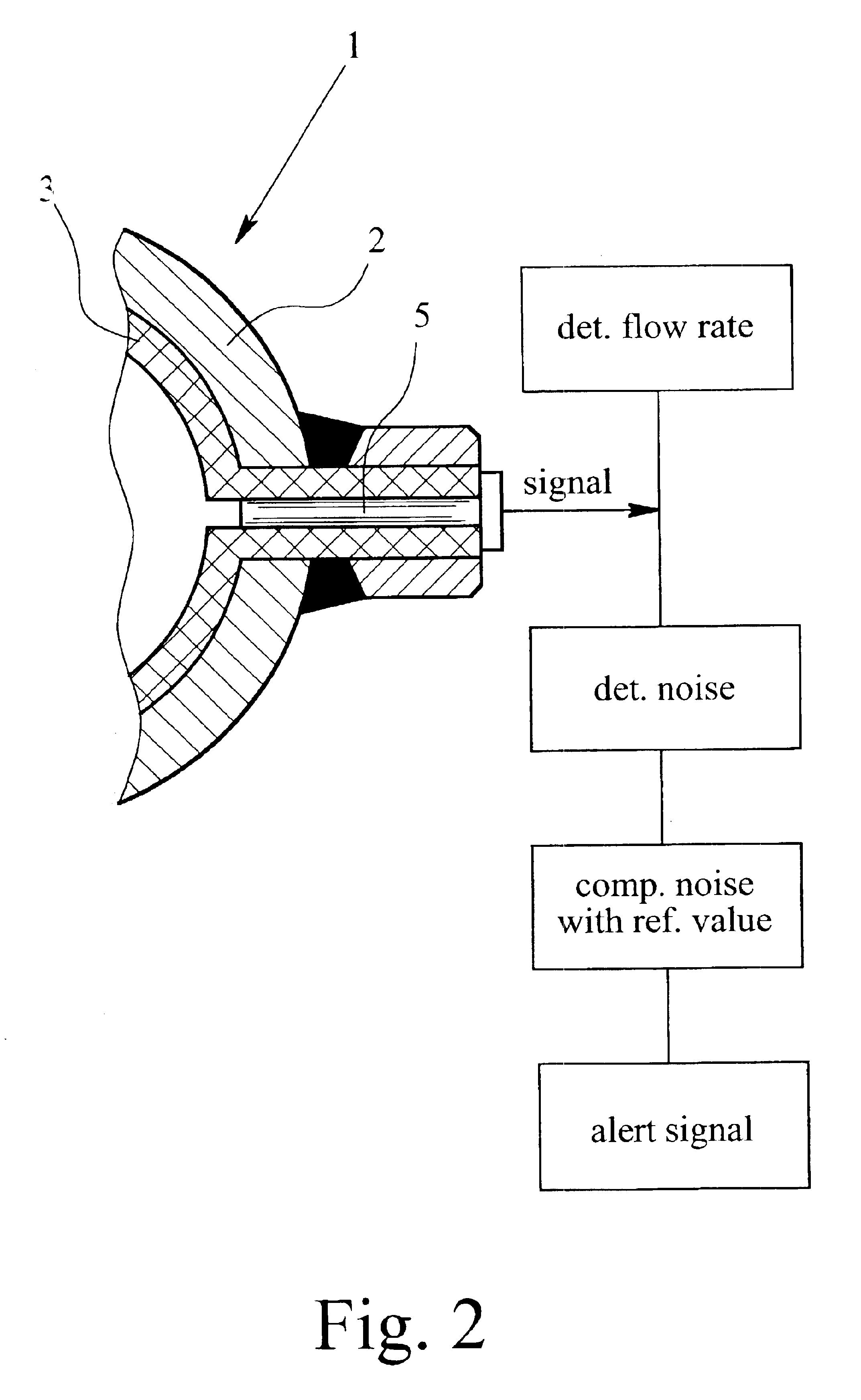
The magnetoinductive flowmeter according to the preferred embodiment of the invention features a measuring conduit 1 composed of a measuring tube 2 and an electrically insulating internal liner 3. The wall of the measuring conduit 1 is provided with a sampling-electrode channel 4. Field coils, not illustrated, generate a magnetic field, inducing an electric voltage in the medium that flows through the measuring conduit 1. This voltage, induced in the medium, is collected by two mutually opposite sampling electrodes of which only one sampling electrode 5 is illustrated. The sampling electrode 5 is so positioned in the sampling electrode channel 4 that its sampling-electrode head 6 is recessed from the inner wall surface of the measuring conduit 1, i.e. the inner wall surface of the liner 3. This leaves an empty section or space 7 in the sampling electrode channel 4 in front of the sampling-electrode head 6. That space 7 is completely free, without any insert, cap or cover, thus allow...


PUM


Abstract

A magnetoinductive flowmeter that serves to measure the flow rate of a moving medium incorporates a measuring conduit, a sampling-electrode channel extending through the wall of the measuring conduit, and a sampling electrode, which sampling electrode is positioned in the sampling-electrode channel in such fashion that its sampling-electrode head is recessed from the inner wall of the measuring conduit. A section of the sampling-electrode channel located in front of the sampling-electrode head and extending up to the interior of the measuring conduit is left as a free space. This results in an improved signal-to-noise ratio of a voltage signal collected at the sampling electrode.

Description

BACKGROUND OF THE INVENTION1. Field of the InventionThis invention relates to a magnetoinductive flowmeter for measuring the flow rate of a moving medium, with a measuring conduit through whose wall extends a sampling-electrode channel, and a sampling electrode that is positioned in the sampling-electrode channel in such fashion that the electrode head is recessed from the inside wall surface of the measuring conduit.2. Description of the Prior ArtMagnetoinductive flowmeters have essentially been well-known for some time and have been employed in a variety of applications. The basic principle of a magnetoinductive flowmeter for measuring the flow rate of fluids and liquids goes all the way back to Faraday who, as early as 1832, suggested utilizing the principle of electrodynamic induction for measuring flow rates. According to Faraday's law of induction, a flowing medium that contains charge carriers and travels through a magnetic field will generate an electric field intensity perp...

Claims


Application Information

Patent Timeline
IPC IPC(8): G01F1/58G01F1/56
CPCG01F1/584
Inventor HOFMANN, FRIEDRICHVAN WILLIGEN, ARNOULD L.POORTMANN, BOSBOOM J.
Owner AGRI GENETICS
Why Eureka
Try Eureka