
Anchor assist

a technology of anchors and rigging, applied in the field of anchors, can solve problems such as damage to the gunnel or the sides of the boa

Inactive Publication Date: 2005-01-18
RICHARDSON KENNY CARL +1
View PDF8 Cites 9 Cited by
  • Summary
  • Abstract
  • Description
  • Claims
  • Application Information

AI Technical Summary

Benefits of technology

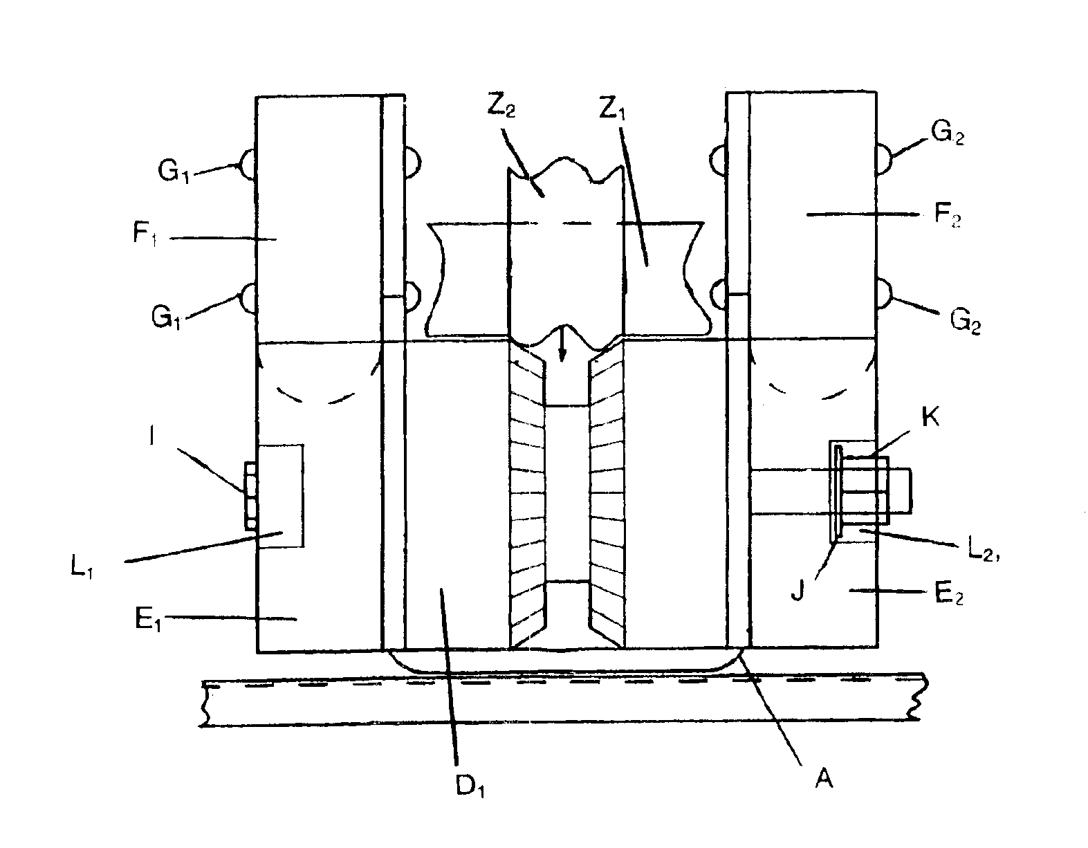
The anchor assist device is a wider and higher type of “U” shaped type of boat bow chock-rope guide and anchor staging and storage device which allows buoy type anchor retrieval devices to be pulled through the guide without rope removal. It is designed to allow pulling of the anchor via the buoy retrieval system with the rope routed through the device and attached to the bow or other forward cleat point. It is designed to allow the resting anchor to be easily released from its storage-rest position by raising the anchor rope. This tipping of the anchor allows it to release and roll off the bow rest position into the water. The “U” shaped rest, formed by a frame, gusset platform, rollers and guides, provides a sure rope guide and a secure platform for anchor retrieval and storage. A pin device is used to secure the anchor in the rest position during transition or travel. The anchor lies on the device in the rest position, ready to release without the pin device installed. The anchor is in position for the next release when brought to rest in the anchor assist device. The device works equally well without mechanical buoy type retrievers for anchoring and retrieving the anchor manually.
A tapered center roller guide (of UHMW polyethylene or similar material), of large enough diameter allows the transition from rope end, past the lifter hardware and on to the anchor chain (when used) and directly to the anchor, so that the anchor settles to rest in the bracket on the gusset platform and center roller guides in the bracket. A rope groove is cut in the center of the center roller guide to help provide a positive center line position for the rope while at anchor.
The design helps reduce the chance that an anchor being retrieved would swing and hit the sides of the boat as the anchor is pulled. The anchor assist device keeps the anchor away from the sides and gunnel as it comes into the rest position.

Problems solved by technology

Other pullers require removing the rope from the anchor chock and pulling the buoy, retrieving mechanism, lead chain (when used) and anchor up and over the side of the bow, often damaging the gunnel or sides of the boat.

Method used


Image

  • Anchor assist
  • Anchor assist
  • Anchor assist

Examples


Embodiment Construction

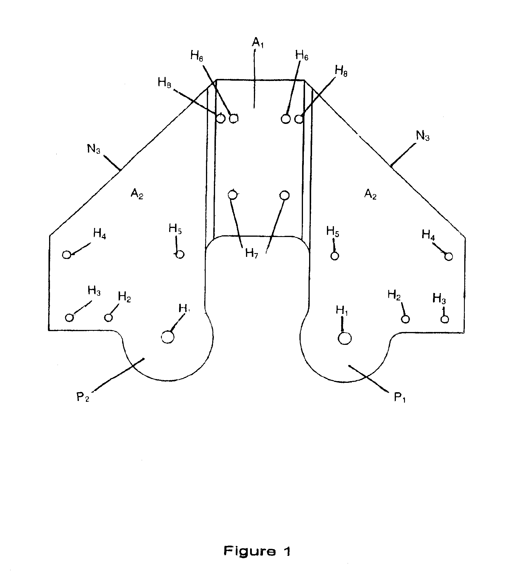
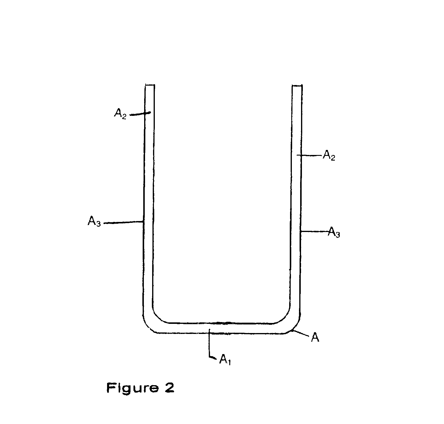
A “U” shaped bracket shown in FIGS. 1 and 2 includes the base A1 and two sides A2 of the anchor device AA. A gusset plate B is welded in place between the two sides A2 forming an anchor rest platform, and can be adjusted to fit a milled countersink to improve consistency in placement. A tapered center roller D1 is installed at the front D2 of the anchor assist device AA, between two sides A2. The center roller D1 may be formed of ultra high molecular weight (UHMW) polyethylene and is 3½ inches in diameter. Horizontal roller guides E1 and E2 are interchangeably affixed to either side A2 and are also formed of 3½ inch diameter UHMW polyethylene. Outer vertical guides F1 and F2 are also interchangeably affixed to either side A2 and are formed of 1½ inch diameter UHMW polyethylene with a 3½ inch height. The vertical guides F1 and F2 are affixed to the sides A2 by screws G1 and G2, which may be {fraction (1 / 4)} inch diameter, threaded stainless steel countersunk or Phillips pan head scre...


PUM


Abstract

The An anchor retrieval assist device including a “U” shaped type of boat bow chock-rope guide and anchor staging and storage device which allows buoy type anchor retrieval devices to be pulled through the guide without rope removal. It is designed to allow pulling of an anchor via the buoy retrieval system with a rope routed through the device and attached to a forward cleat on a boat. The anchor can be easily released from its storage-rest position by raising the anchor rope, tipping the anchor to allow it to roll off the bow rest position into the water. A pin is provided to secure the anchor in the rest position. The device works equally well with or without mechanical buoy type retrievers for anchoring and retrieving the anchor manually.

Description

BACKGROUND AND SUMMARY OF THE INVENTIONThe anchor assist device was designed and created for boat anchoring to fill a void in the market for boat anchoring and retrieval of anchor systems utilizing mechanically designed anchor float retrieval systems. Other pullers require removing the rope from the anchor chock and pulling the buoy, retrieving mechanism, lead chain (when used) and anchor up and over the side of the bow, often damaging the gunnel or sides of the boat.In this device, the anchor puller and buoy are able to be pulled through the wider roller and guide system without removal from the rope guide. The primary design difference, not previously available, is the use of a metal step roller bracket which is designed to have a wide enough throat space to accommodate the various buoy puller mechanisms (such as, but not limited to EZ Marine lifter, Ironwood Pacific puller, and other types) with vertical guides to keep the rope in the device while the puller transitions through i...

Claims


Application Information

Patent Timeline
IPC IPC(8): B63B21/22B63B21/00
CPCB63B21/22
Inventor RICHARDSON, KENNY CARLRICHARDSON, LARRY DONN
Owner RICHARDSON KENNY CARL
Learn More