Control apparatus and control method of internal combustion engine

a control apparatus and internal combustion engine technology, applied in the direction of electric control, ignition automatic control, machines/engines, etc., can solve the problems of inability to accurately detect the intake air amount in the engine transient state where the intake air amount is high, inability to accurately detect the intake air amount,

Inactive Publication Date: 2005-01-18
HITACHI LTD
View PDF5 Cites 6 Cited by
  • Summary
  • Abstract
  • Description
  • Claims
  • Application Information

AI Technical Summary

Problems solved by technology

In such an engine, since there occurs a detection delay from the time when the air amount actually sucked into a cylinder is changed until such a change is detected by the air amount detecting means (air flow meter), in particular, it is impossible to accurately detect the intake air amount in an engine transient state where the intake air amount is changed.
Further, in such an engine, generally, since an opening of a throttle valve disposed in an intake passage is controlled so that a predetermined negative pressure can be obtained, that is, so that an intake pressure becomes constant, it is impossible to detect the intake air amount even if such an intake pressure is detected as in the above conventional technique.
Therefore, with the conventional control device as mentioned above, in an internal combustion engine provided with a variable valve mechanism that varies a valve operating characteristic of an intake valve, where an intake air amount control is performed by varying the valve operating characteristic of the intake valve by the variable valve mechanism, it is impossible to accurately detect (calculate) the intake air amount.
Especially, in the case where the intake air amount is changed, due to the detection delay, engine controlled variable, such as a fuel injection quantity and the like, to be set according to the intake air amount, is not calculated corresponding to the change, resulting in a possibility of the reduction of engine drivability and emission performance.

Method used


Image

  • Control apparatus and control method of internal combustion engine
  • Control apparatus and control method of internal combustion engine
  • Control apparatus and control method of internal combustion engine

Examples


second embodiment

Also in the second embodiment, it is possible to realize the fuel injection quantity control and the ignition timing control accurately corresponding to the change in intake air amount in the transient state.

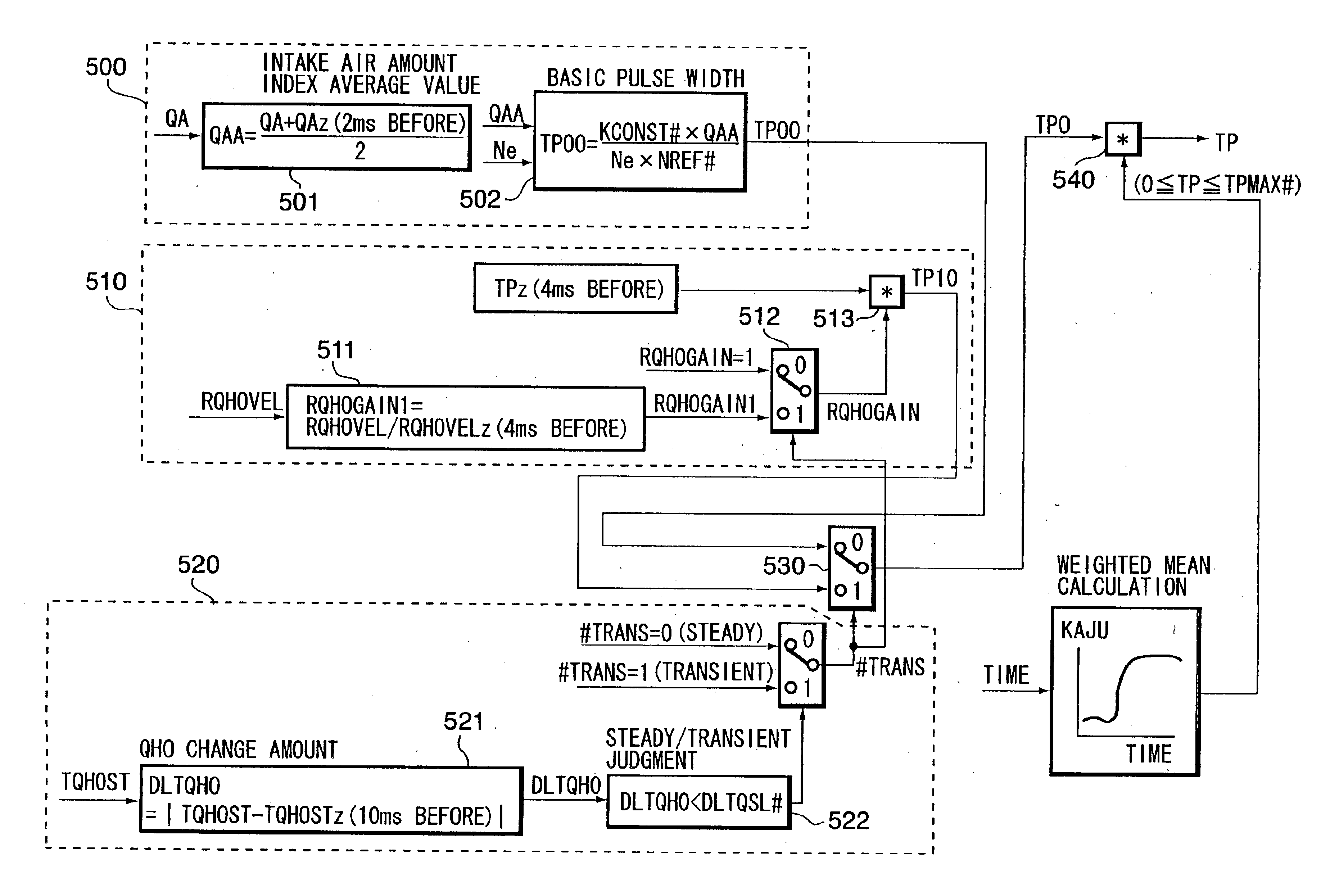
As described in the above, according to the above embodiments, the constitution is such that the intake air amount controlled by the intake valve is calculated based on the valve operating characteristic of intake valve, and the newest engine controlled variable is calculated based on the change between the newest intake air amount calculation value and the past intake air amount calculation value, and the previously set engine controlled variable, to control the engine based on the calculated newest engine controlled variable. In such a constitution, since the present (newest) engine controlled variable is calculated, using the engine controlled variable set in the past, and the change (change rate or change amount) in the intake air amount calculation value from the past, whic...


PUM


Abstract

In an internal combustion engine provided with a variable valve mechanism that varies a valve operating characteristic (valve lift amount and valve operating angle) of an intake valve, the valve operating characteristic of the intake valve is detected and an intake air amount controlled by the intake valve is calculated based on the detected valve operating characteristic. Then, a change (change rate, change amount) between the newest intake air amount calculation value and a past intake air amount calculation value is calculated, and the newest engine controlled variable is calculated based on the change and engine controlled variable (basic fuel injection quantity and the like) set in the past, and then the calculated newest engine controlled variable is output for executing an engine control.

Description

FIELD OF THE INVENTIONThe present invention relates to a control apparatus and a control method of an internal combustion engine provided with a variable valve mechanism that varies a valve operating characteristic of an intake valve, and in particular, to a technique for accurately calculating engine controlled variable according to a cylinder intake air amount.RELATED ART OF THE INVENTIONHeretofore, there has been known an engine control device in which an intake air amount is calculated based on an air amount detected by air amount detecting means, such as an air flow meter, and a detected intake pressure, to calculate a fuel injection quantity based on the intake air amount (refer to Japanese Unexamined Patent Publication 11-62639).However, there has been developed an engine in which an intake air amount control is performed by varying a valve operating characteristic of an intake valve. In such an engine, since there occurs a detection delay from the time when the air amount ac...

Claims


Application Information

Patent Timeline
Patent Type & Authority Patents(United States)
IPC IPC(8): F02D41/00F02D13/02F01L13/00F02D41/18F02D41/10F01L1/34F02D41/02F02D41/04F02D41/20F02D45/00
CPCF01L1/022F01L13/0026F02D13/0207F02D13/0261F02D41/0002Y02T10/42F01L2001/34453F01L2013/0073F01L2201/00F01L2800/00F02D41/10F02D41/18F02D2041/001F02D2200/0402Y02T10/18F01L1/024Y02T10/12Y02T10/40
Inventor IIZUKA, ISAMUMACHIDA, KENICHI
Owner HITACHI LTD
Why Eureka
Try Eureka