Urinary-control device

a urethra clamp and control device technology, applied in the field of urethra clamps, can solve the problems of incontinence, pain, inconvenience, etc., and achieve the effect of not inflicting pain, trauma, damage to skin and underlying tissues, and comfortable wear by users

Inactive Publication Date: 2005-01-18
C&L MEDICAL SUPPLY CORP
View PDF15 Cites 27 Cited by
  • Summary
  • Abstract
  • Description
  • Claims
  • Application Information

AI Technical Summary

Benefits of technology

Another advantage of the urinary-control device of the present invention is that it uses variable adjustment to enable application of different pressures to the penis to accommodate needs of individual users.
Another advantage of the urinary-control device of the present invention is that it does not inflict pain, trauma, and/or damage to the skin and underlying tissues of the penile shaft.
Still another advantage of the urinary-control device of the present invention is that it is more comfortably worn by the user than suc...

Problems solved by technology

Incontinence—the uncontrolled and undesired passage of urine—is a problem faced by many men and, especially, older men.
Incontinence may be caused by, for example, medical operations, partial or full sphincter loss, disease, neurological dysfunction, malformation of the urethral valve, and physical deterioration accompanying advancing age such that the natural urethral valve or sphincter is no longer capable of controlling the flow of urine from the bladder.
Whatever the cause, incontinence is a significant problem resulting in distress, embarrassment, inconvenience, and restriction of activities.
While clamping devices of the type known in the related art can create sufficient pressure to stop flow of involuntary urine, they also suffer from the disadvantage in that they often reduce or stop blood flow through the penis.
This unacceptable and sometimes painful amount of pressure is applied to tissues other than the urethra and corpus spongiosum.
Unfortunat...

Method used


Image

  • Urinary-control device
  • Urinary-control device
  • Urinary-control device

Examples


Embodiment Construction

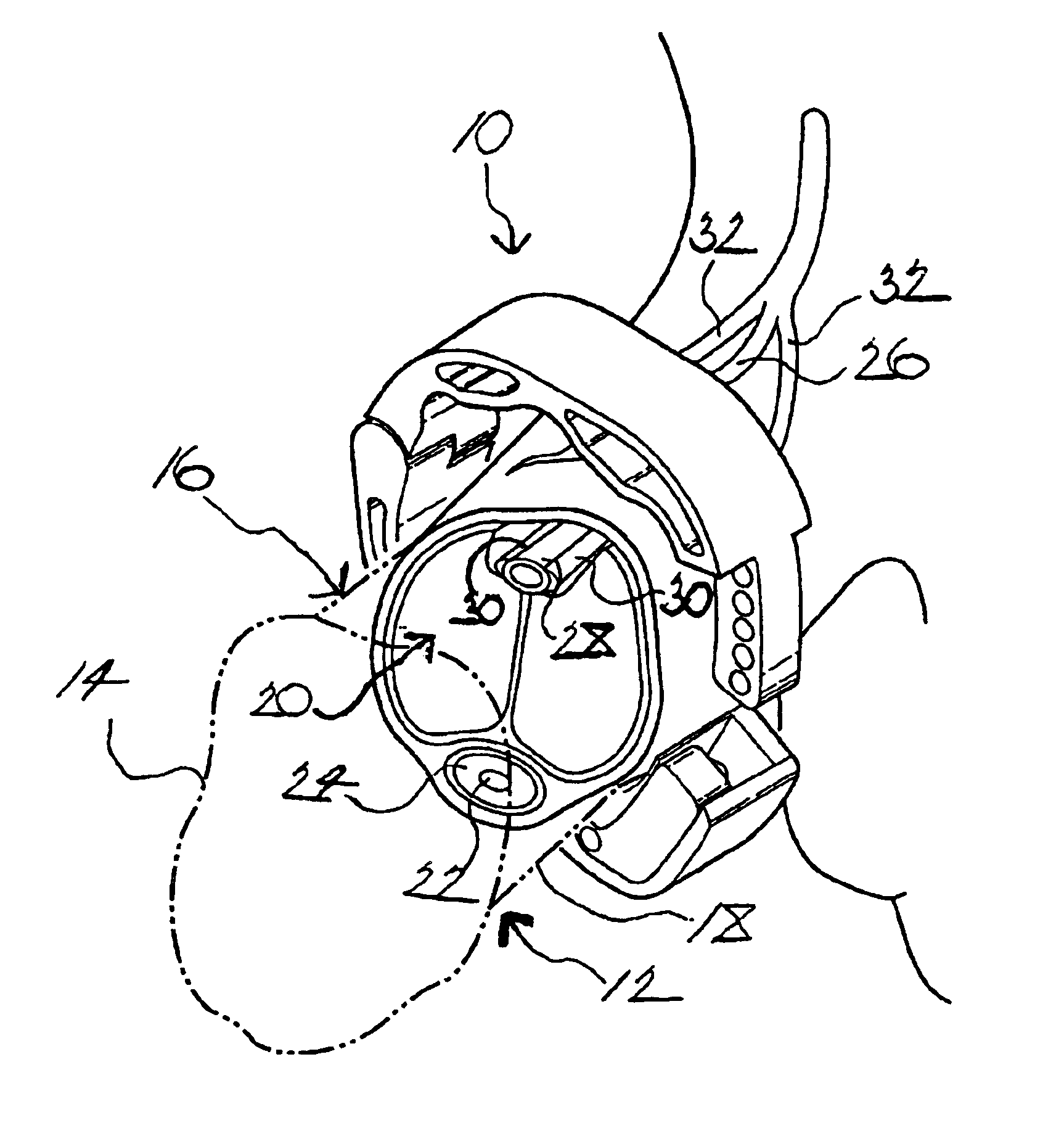
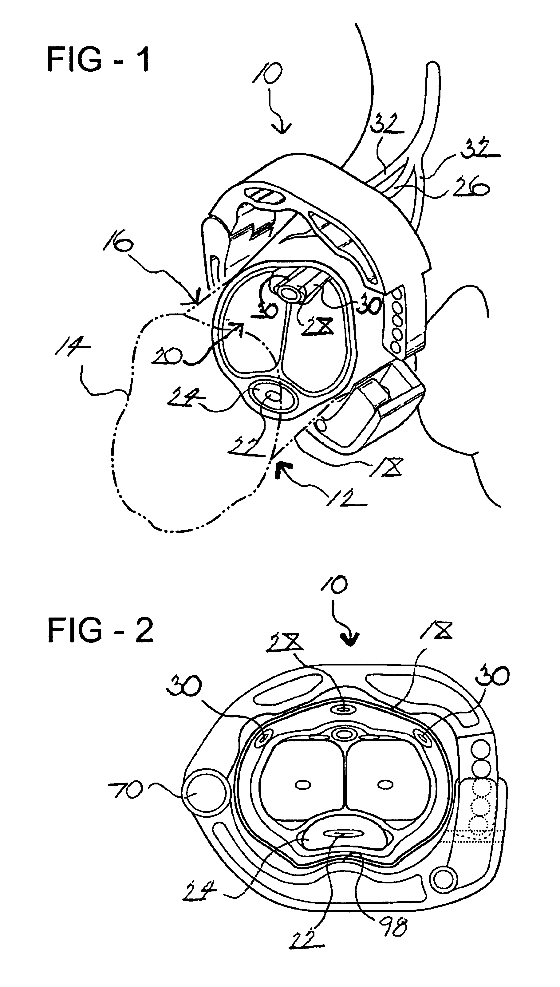
Referring now to the figures, where like numerals are used to designate like structure, a urinary-control device for inhibiting male incontinence is generally indicated at 10. As shown in FIGS. 1, 2, 8B, 8C, and 8D, the device 10 is adapted to be disposed in operative use about a penis, generally indicated at 12. The penis 12 includes a head 14; a shaft, generally indicated at 16, extending substantially longitudinally from an end of the head 14; an epidermal layer 18 covering the shaft 16; and a neurovascular bundle, generally indicated at 20, extending substantially longitudinally through the interior of the shaft 16 beneath the epidermal layer 18. For purposes of description only and not by way of limitation, the neurovascular bundle 20 may include the urethra 22, corpus spongiosum 24, superficial dorsal vein 26, subcutaneous dorsal vein 28, subcutaneous lateral veins 30, and superficial lateral veins 32. However, those having ordinary skill in the art will appreciate that the ne...


PUM


Abstract

A urinary-control device for inhibiting male incontinence includes upper and lower clamping members each having a substantially arcuate inner surface adapted to be disposed about a portion of a penis. A hinge allows articulated movement of the upper and lower clamping members relative to one another. A self-locking mechanism is adapted to adjustably lock the clamping members together, thereby mounting the device to the penis. A protrusion is formed on the inner surface of the lower clamping member and extends toward the inner surface of the upper clamping member to collapse the urethra to inhibit flow of urine therethrough when the device is mounted to the penis. A plurality of vein-relief portions are disposed spaced from one another and formed on the inner surface of the upper clamping member such that the device does not constrict blood flow through the penis when the device is mounted to the penis.

Description

BACKGROUND OF THE INVENTION1. Field of the InventionThe present invention relates, generally, to a urinary-control device employed to combat male incontinence and, more particularly, to a urethra clamp.2. Description of the Related ArtIncontinence—the uncontrolled and undesired passage of urine—is a problem faced by many men and, especially, older men. Incontinence may be caused by, for example, medical operations, partial or full sphincter loss, disease, neurological dysfunction, malformation of the urethral valve, and physical deterioration accompanying advancing age such that the natural urethral valve or sphincter is no longer capable of controlling the flow of urine from the bladder. Whatever the cause, incontinence is a significant problem resulting in distress, embarrassment, inconvenience, and restriction of activities.It is known in the related art to prevent involuntary flow of urine in incontinent males by clamping the penis via particular devices that cause pressure to b...

Claims


Application Information

Patent Timeline
IPC IPC(8): A61F5/41
CPCA61F2/0054A61F5/41Y10S128/25A61F2005/414
Inventor PARKES, RICARD A.
Owner C&L MEDICAL SUPPLY CORP
Why Eureka
Try Eureka