This helps you quickly interpret patents by identifying the three key elements:
Problems solved by technology
Method used
Benefits of technology
Benefits of technology
In order to prevent the vehicle cabin from being deformed, it is supposed to reinforce the environs of the joints of the rear-side mount parts and also enhance rigidity of the front part of the vehicle cabin. However, this measures cause a weight of the structure to be increased with the disadvantage in manufacturing cost.
Under the above circumstance, it is an object of the present invention to provide a front body structure which can disperse and transmit a collision input (load) due to the vehicle front collision to a floor framework member forming a cabin floor of the vehicle effectively.
Problems solved by technology
Consequently, there is a possibility that the joints of the rear-side mount parts moves backward to cause the vehicle cabin to be deformed.
However, this measures cause a weight of the structure to be increased with the disadvantage in manufacturing cost.
Method used
Image
Click on the blue label to locate the original text in one second.
Reading with bidirectional positioning of images and text.
Examples
first embodiment
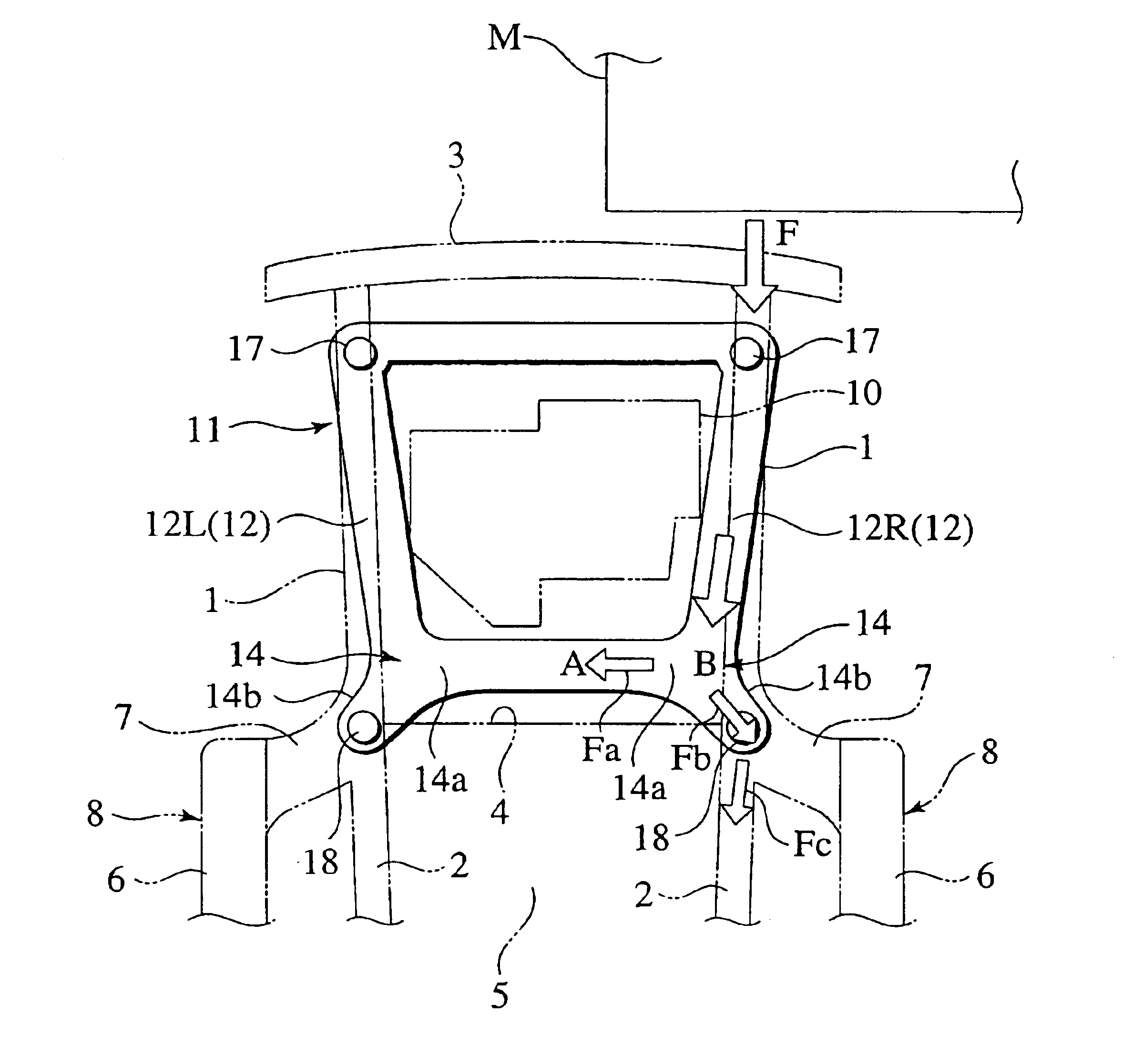
mentioned above, as shown in FIG. 4, when the vehicle has an offset collision with an obstacle M through a vehicle's front-and-right side, the collision load F acts on the front end of the right side frame 12R of the subframe 11 in the axial direction.
The collision load (input) F is dispersed, at the forked part 14 at the rear end of the right side frame 12R, into a load component Fa and a load component Fb. The load component Fa is transmitted to the left side frame 12L through the inside branch part 14a and the rear frame 13 along the first route A directing to the inside of the side frame 12R in the width direction of the vehicle. On the other hand, the load component Fb is transmitted to the floor framework member 8 through the outside branch part 14b along the second route B directing to the outside of the side frame 12R in the width direction of the vehicle.
At the joint part of the rear-side mount part 18 in the second route B, there is remained a load component Fe in the fore...
second embodiment
According to the invention, the rear frame 13 of the subframe 11 is curved upward.
In addition to the effects of the first embodiment, while transmitting the load component Fa, which has been dispersed at the forked part 14 of the side frame 12R to direct the first route A, to the other side frame 12L through the rear frame 13, the load component Fa causes the rear frame 13 to be plastically formed in the curved direction, allowing the collision energy to be absorbed partially.
Additionally, since the rear frame 13 is curved upward, it is possible to avoid the interference of the subframe 11 with other components (for example, exhaust pipes, a drive shaft, etc.) extending from the inside of the front compartment FC to the underside of the floor 5.
third embodiment
FIG. 7 shows the invention. In this embodiment, the subframe 11 is provided, behind the forked parts 14, with notches 19 each serving as a weakened part between the inside branch part 14a and the outside branch part 14b.
According to the embodiment, owing to the provision of the notches 19 each positioned at a boundary part between the inside branch part 14a and the outside branch part 14b, the collision load transmitted from the front side of one side frame 12 in the axial direction causes the forked part 14 to be deformed as if the above boundary part were torn with the notch 19 as the starting point of tear, whereby the conversion of load in the width direction of the vehicle to the first route A and the second route B can be promoted.
PUM
Abstract
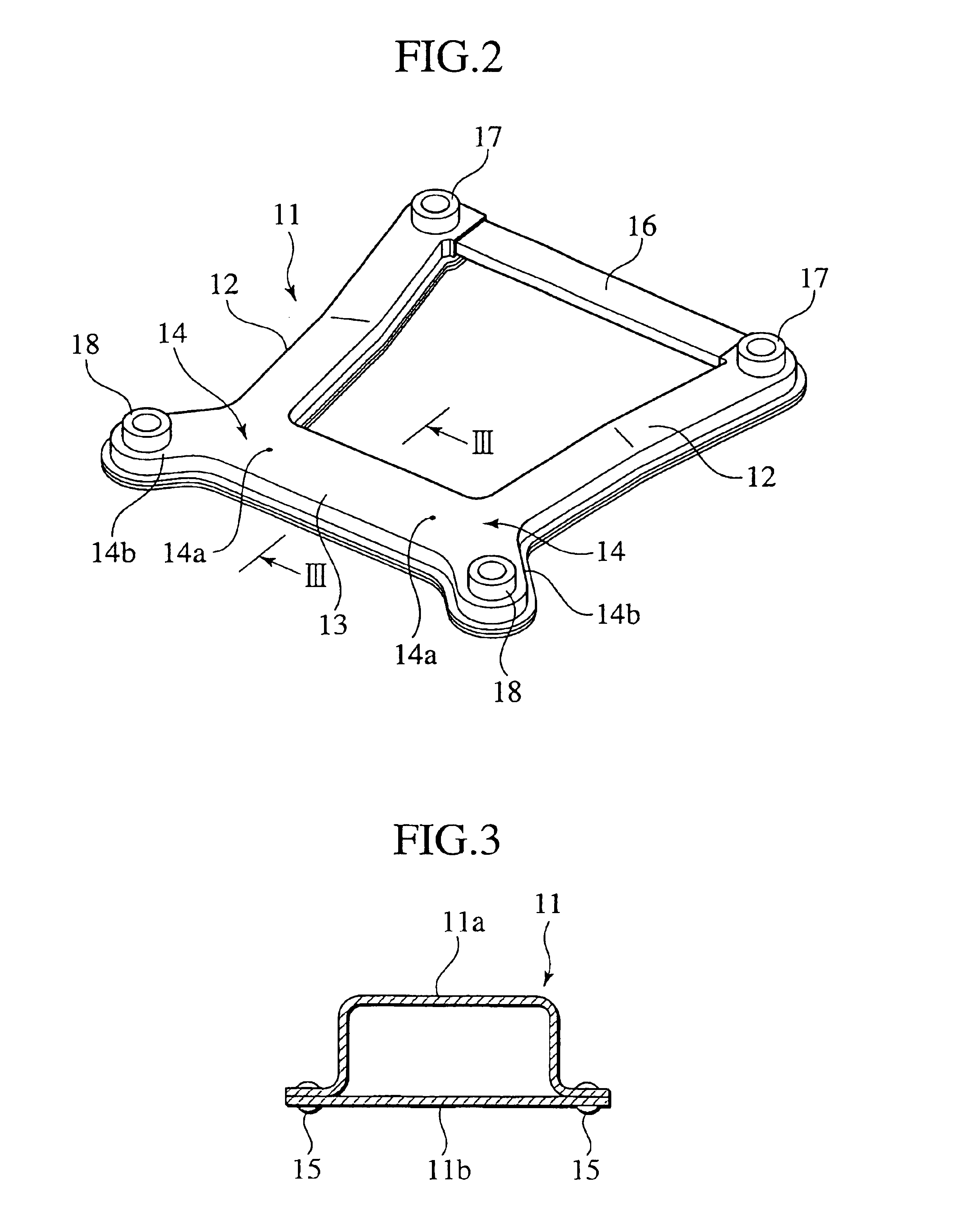
A front body structure is provided to disperse an impact load to a floor framework member through a rear end of a subframe effectively. The subframe 11 includes a left side frame 12L, a right side frame 12R and a rear frame 13. Each of the side frames 12L, 12R includes a forked part 14 having an inside branch part 14a pointing to a vehicle's inside in a width direction of the vehicle along a first route A and an outside branch part 14b pointing to a vehicle's outside in the width direction along a second route B. In operation, if an impact load F due to an offset front collision is applied on the side frame 12 in concentration, then the load F is divided into a load component Fa to be transmitted to the other side frame 12L through the inside branch part 14a and the rear frame 13 along the first route A and another load component Fb to be transmitted to the floor framework member 8 through the outside branch part 14b along the second route B.
Description
BACKGROUND OF THE INVENTION1. Field of the InventionThe present invention relates to a front body structure for a vehicle.2. Description of Related ArtIn general, the front body structure for a vehicle is designed so as to absorb a collision energy when at least one side member forming a fore-and-aft directional framework member of a front compartment collapses in the axial direction of the side member.However, for reasons that the side member is not always formed straightly and a power unit (e.g. heavy engine, drive motor) is attached to the side members, there is a possibility that the side members are deformed in bending at the vehicle collision.Additionally, when the vehicle has an offset front collision, a problem arises in the impossibility of absorbing a collision energy sufficiently since a collision input (load) concentrates on one side member. In order to solve the above problem, Japanese Patent Application Laid-open No. 9-119322 discloses a structure that is directed to i...
Claims
Application Information
Patent Timeline
Application Date:The date an application was filed.
Publication Date:The date a patent or application was officially published.
First Publication Date:The earliest publication date of a patent with the same application number.
Issue Date:Publication date of the patent grant document.
PCT Entry Date:The Entry date of PCT National Phase.
Estimated Expiry Date:The statutory expiry date of a patent right according to the Patent Law, and it is the longest term of protection that the patent right can achieve without the termination of the patent right due to other reasons(Term extension factor has been taken into account ).
Invalid Date:Actual expiry date is based on effective date or publication date of legal transaction data of invalid patent.

