

Hemodialysis system
Inactive Publication Date: 2005-01-18
MIRIMEDICAL
View PDF5 Cites 138 Cited by
- Summary
- Abstract
- Description
- Claims
- Application Information
AI Technical Summary
Benefits of technology
[0012]The present invention provides an improved dialysis apparatus and procedure that mitigate various drawbacks of the type described above.
Problems solved by technology
All known arrangements have certain drawbacks that adversely affect the quality and / or speed of a complete dialysis procedure.
There are several limitations to the current application of DHF:1) Patient selection.
These add risk to the treatment and liability to the clinic that alters the equipment.
However, new machines are being produced which have wider TMP and arterial pressure ranges that permit the pressures achieved during DHF.3) If lower blood flows (<550 ml / min) are used with the existing set up of DHF, there is an increased concern of dialyzer clotting as plasma water is ultrafiltered, thereby hemoconcentrating the blood in the first dialyzer.
The current therapy requires full opening of the clamp at low blood flows, which reduces the ultrafiltration capability of the system.
Method used
View moreImage
Smart ImageViewing Examples

Examples
first embodiment
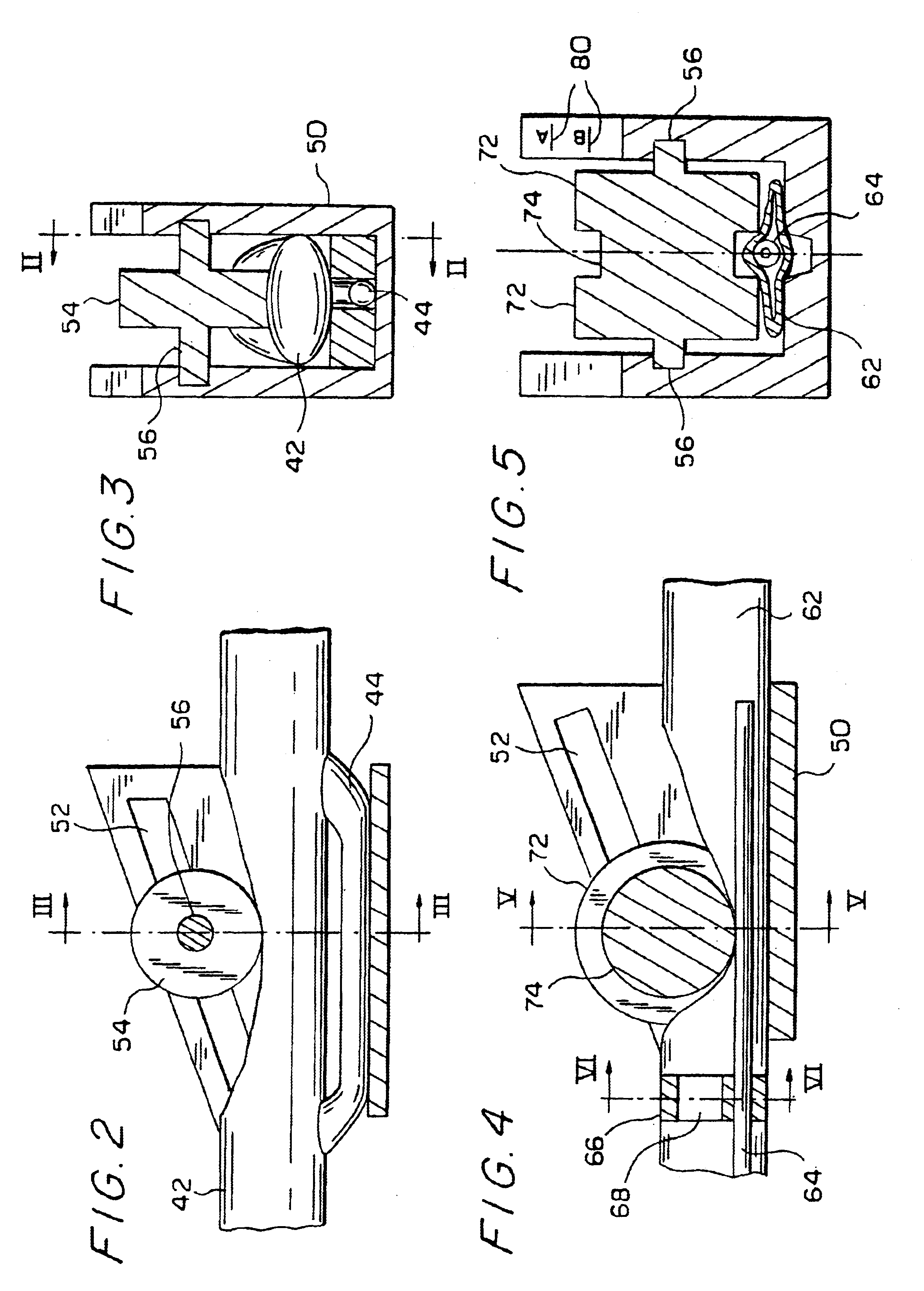
class="d_n">[0026]FIG. 3 is a cross-sectional view taken along line III—III of FIG. 2 of a connecting device according to the invention.
second embodiment
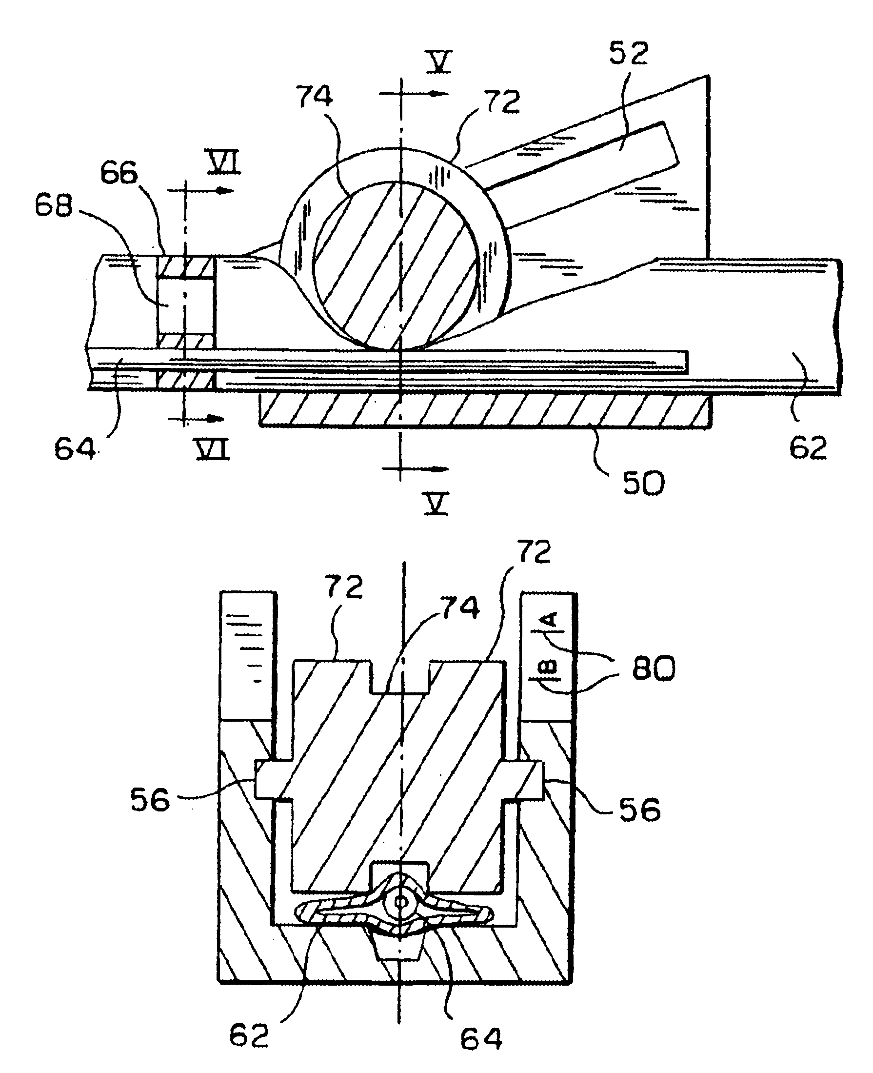
[0027]FIGS. 4 and 5 are views similar to those of FIGS. 2 and 3, respectively, of a connecting device according to the invention.
[0028]FIG. 6 is a cross-sectional view taken along line VI—VI of FIG. 4.
[0029]FIG. 7 shows another embodiment of a connecting device according to the invention.
[0030]FIG. 8 is a simplified pictorial view showing another embodiment of a connecting device according to the invention.
Login to View More PUM
 Abstract
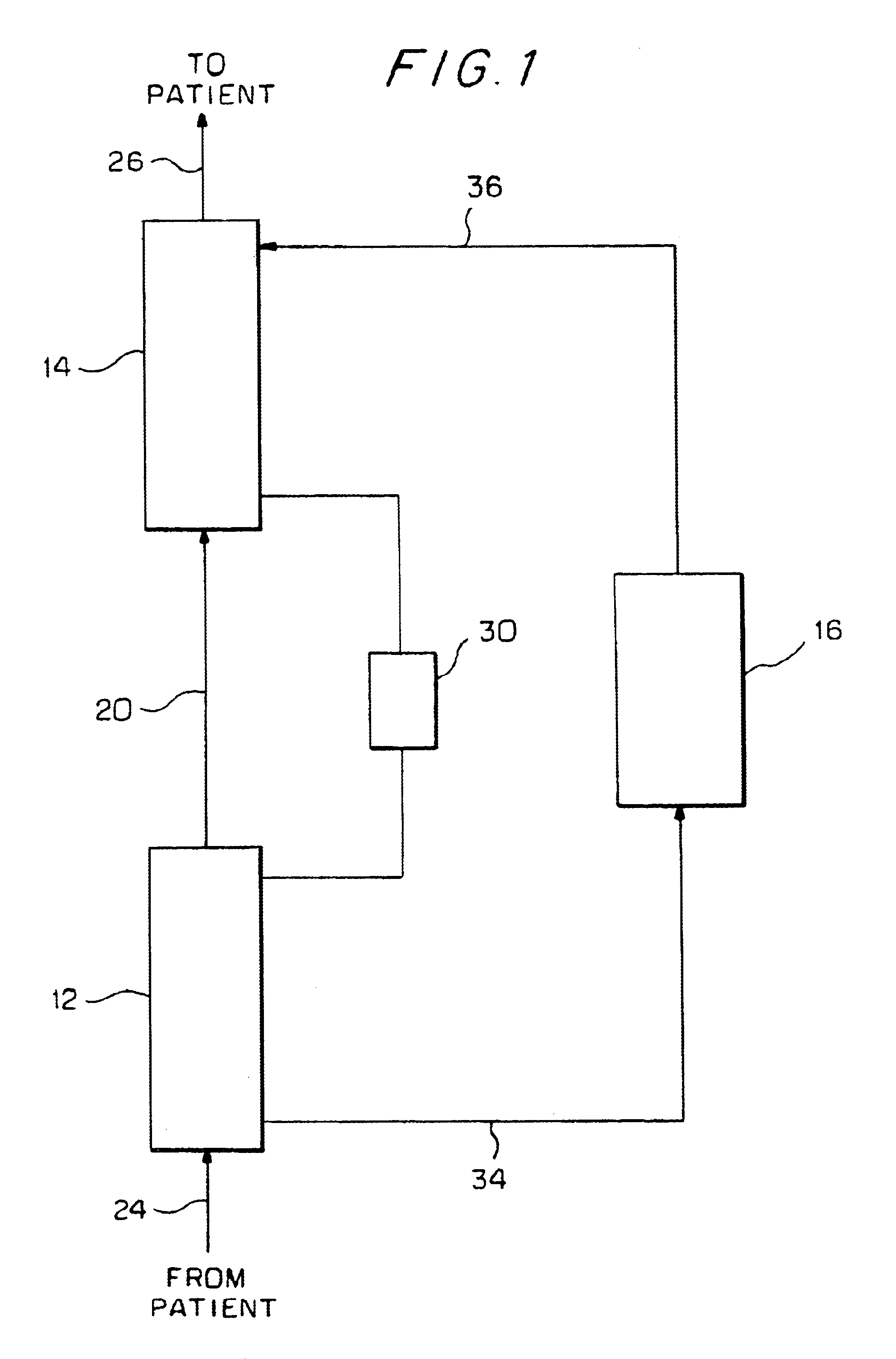
An apparatus and method for use in blood dialysis. The apparatus includes: two dialyzers each containing a semipermeable membrane that divides the dialyzer into a blood compartment and a dialysate compartment; a blood compartment connecting line connecting the blood compartments of the dialyzers together in series; blood connecting lines for connecting the blood compartments to the vascular system of a patient; a dialysate compartment connecting unit connecting the dialysate compartments of the dialyzers together in series; and dialysate connecting lines for connecting the dialysate compartments to a dialysis machine. The dialysate compartment connecting unit includes an adjustable flow varying device for controllably setting the rate of the flow of dialysate through the connecting unit.
Description
BACKGROUND OF THE INVENTION[0002]The present invention relates to hemodialysis for removing blood-borne uremic toxins and by-products of metabolism from the blood of patients suffering from renal failure.[0003]This procedure is performed in dialysis apparatus generally composed of one or more dialyzers in which a blood compartment is separated from a dialysate compartment by a filter structure and a dialysis machine that controls the rate of flow and composition of the dialysate and monitors the dialysis procedure.[0004]Apparatus of this type is available in a variety of forms. For example, the apparatus may be composed of two dialyzers whose respective compartments are connected in parallel or series. Each such form of construction has advantages and disadvantages. All known arrangements have certain drawbacks that adversely affect the quality and / or speed of a complete dialysis procedure.[0005]A typical parallel arrangement is disclosed in U.S. Pat. No. 6,117,100.[0006]Double high...
Claims
Login to View More Application Information
Patent Timeline
 IPC IPC(8): A61M37/00B01D63/00C02F9/00C02F1/44A61M1/34A61M39/28B01D61/32
CPCA61M1/34A61M1/3417B01D61/32A61M39/286A61M2205/3334A61M1/36A61M1/16A61M1/3403A61M2205/3331
InventorANDRYSIAK, PHILIPMISHKIN, GARY
OwnerMIRIMEDICAL