Navigational-based speed limit recording and warning system

a technology of speed limit recording and warning system, applied in the direction of position fixation, navigation instruments, satellite radio beaconing, etc., can solve problems such as speeding infractions

Inactive Publication Date: 2005-01-18
CUFER ASSET LTD LLC
View PDF24 Cites 87 Cited by
  • Summary
  • Abstract
  • Description
  • Claims
  • Application Information

AI Technical Summary

Problems solved by technology

Unfortunately, many drivers become distracted or don't see a posted speed limit sign, which results in speeding infractions.

Method used


Image

  • Navigational-based speed limit recording and warning system
  • Navigational-based speed limit recording and warning system
  • Navigational-based speed limit recording and warning system

Examples


second embodiment

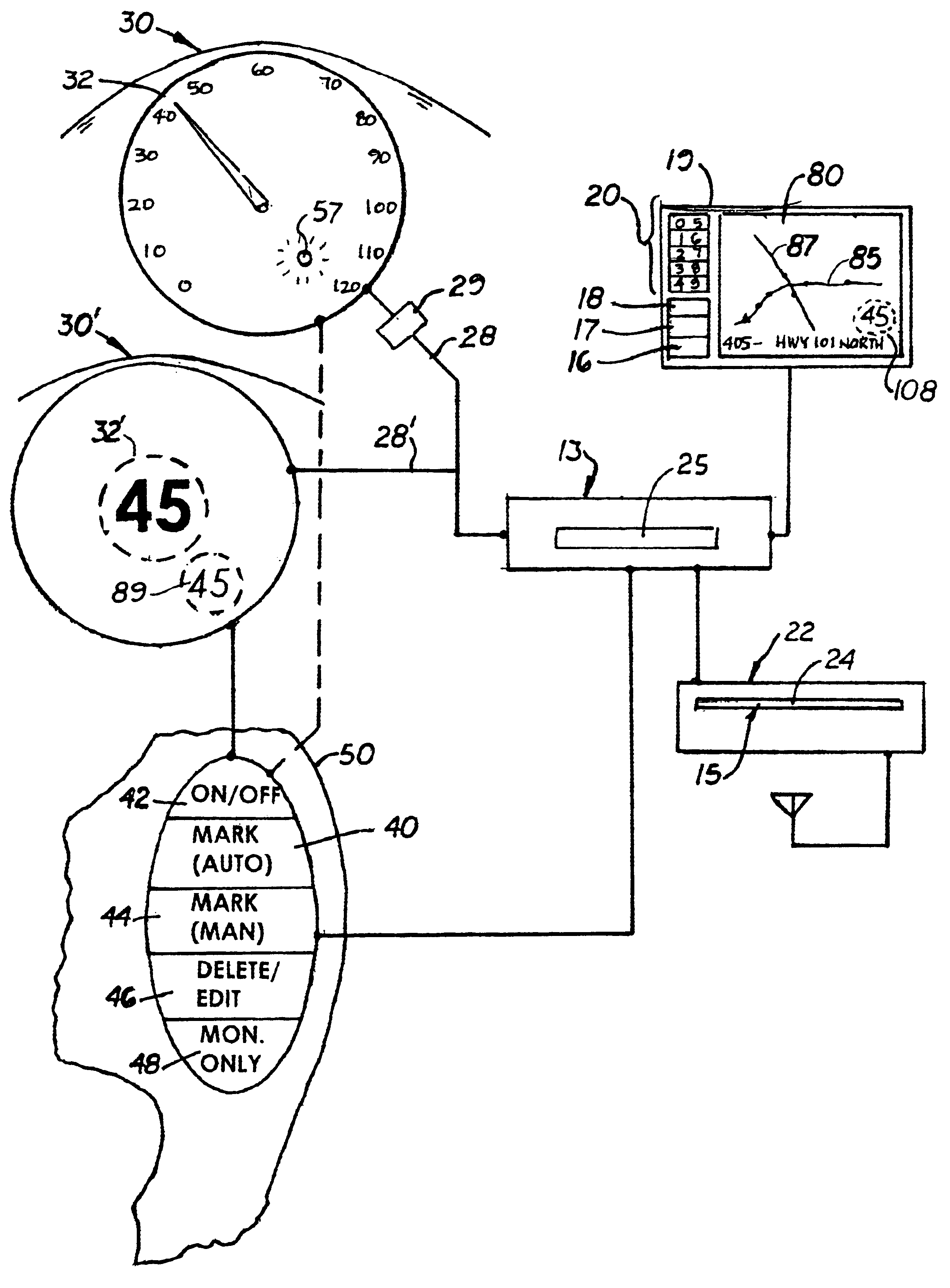
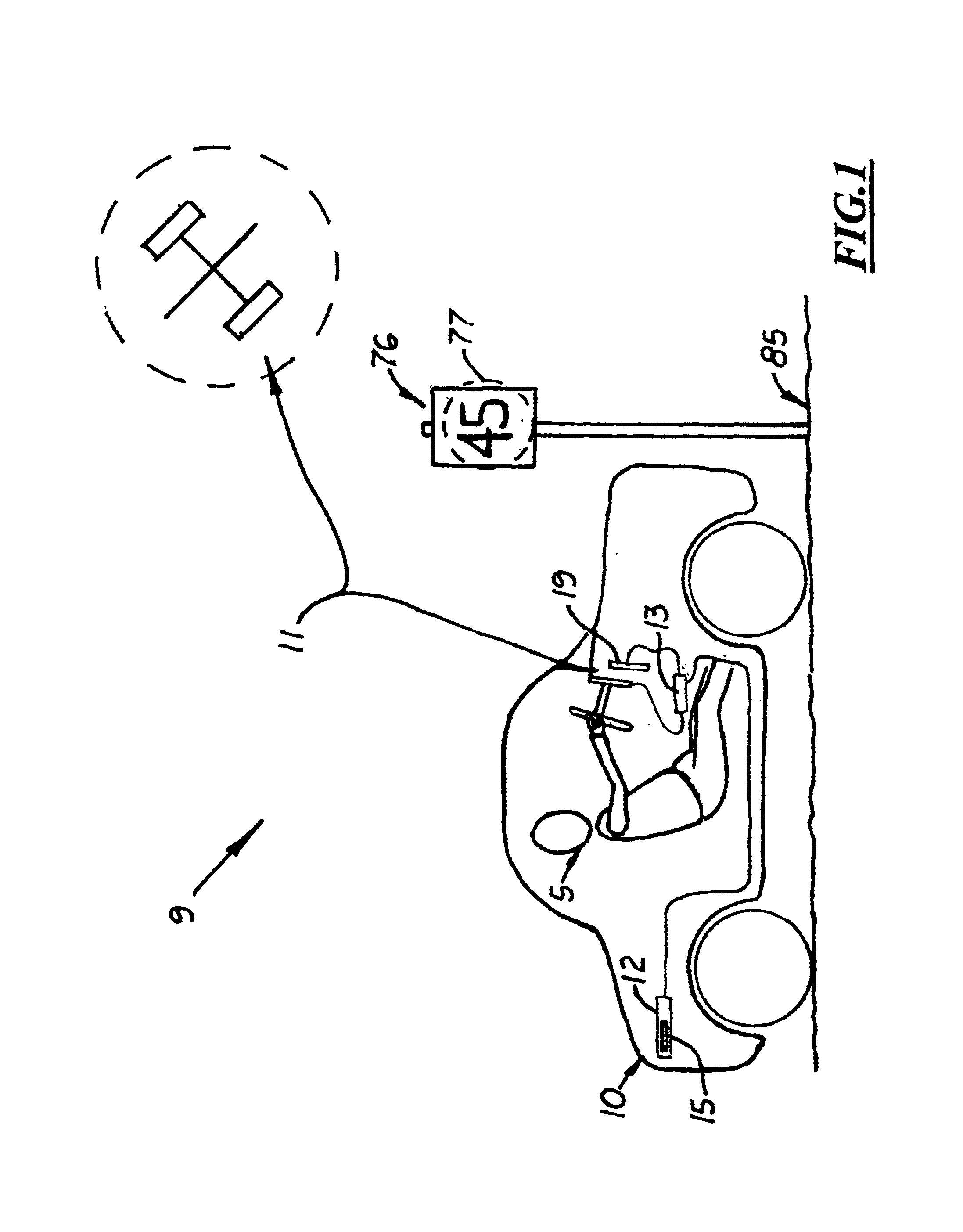
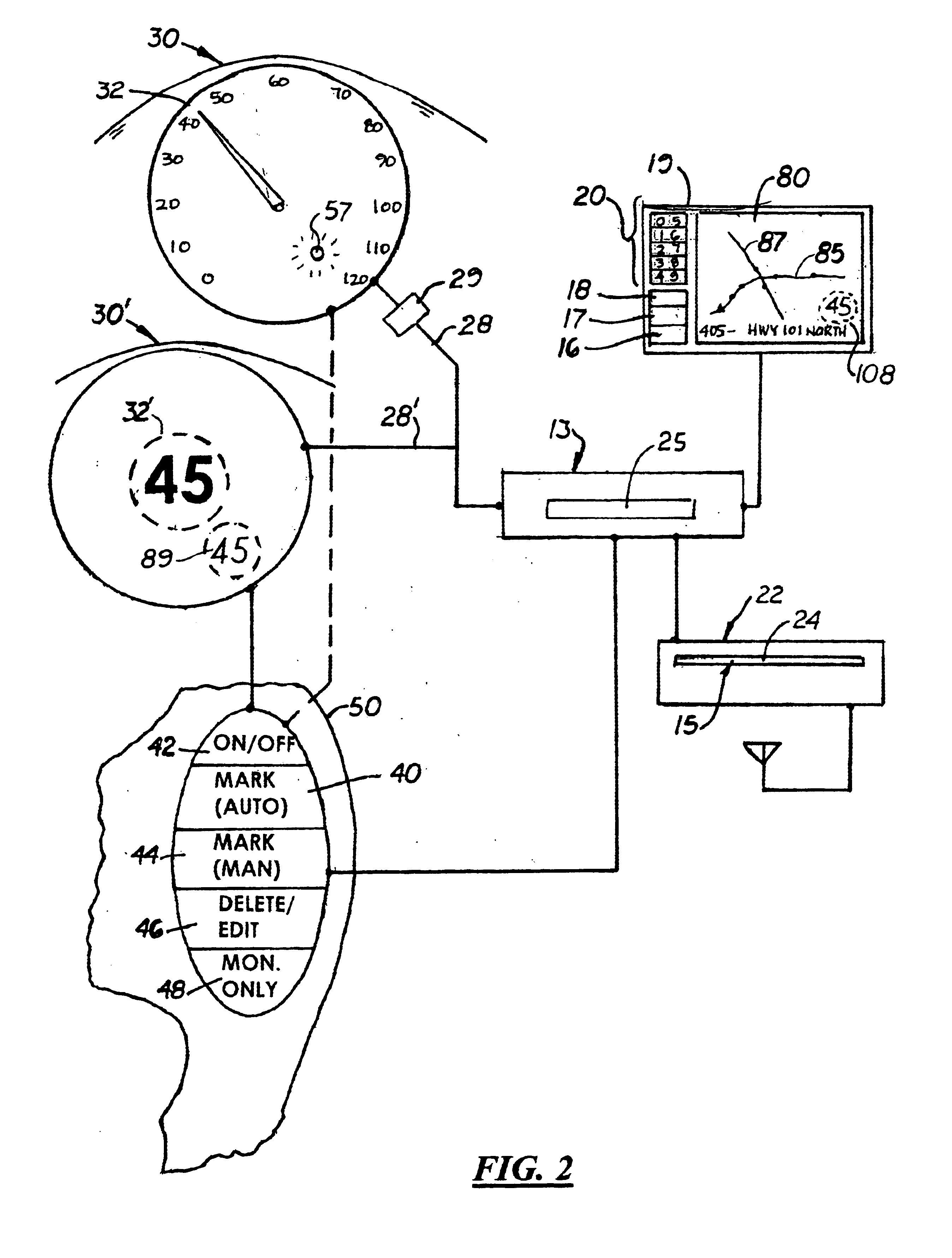
In a second embodiment, shown in FIG. 2, means for inputting the posted speed limit 77 is a link 28, 28′ between the motor vehicle's analog 30 or digital speedometer 30′ that automatically transmits the motor vehicle's current speed information 32, 32′, respectively, to the navigational system 11.

There are two types of “mark” buttons 40, 44. The first “mark” button 40 automatically transmits the motor vehicle's current speed 32, 32′ to the navigational system 11. The second “mark” button 44 is used in combination with the input button 20 that the driver 5 uses to manually input the speed limit 77. The second mark button 44 is typically used to manually input and associate a speed limit 77 to a “mark” location when the motor vehicle 10 is starting or traveling at a speed below the posted speed limit 77. Both the first and second “mark” buttons 40, 44 may be mounted on the steering wheel 50 so that the driver 5 does not have to take his or her hands and eyes off the steering wheel 50 ...

first embodiment

In the first embodiment, the speed limit information is displayed on the display monitor 19 along with roadway information, such as name of roadway, block address, and direction of travel. As mentioned above, the speedometer 30, 30′ and GPS receiver 13 may be coupled together so that the recorded speed limit information 92 from the GPS receiver 13 is displayed on the motor vehicle's dashboard. In another embodiment, the recorded speed limit information 92 is displayed only on the display monitor 19. An LED light or similar signal could then be mounted on the dashboard which is activated by the GPS receiver 13 when the motor vehicle 10 exceeds the recorded speed limit 92. An alternative embodiment could include the use of a digital speedometer 30′ in which the color of the motor vehicle's numeric speed is “green” when the motor vehicle 10 was at or below the recorded speed limit 89 and “red” when above the recorded speed limit 89.

Operation

The navigation system 11 is first activated s...


PUM


Abstract

A motor-vehicle navigation-based speed limit recording and warning system designed to automatically inform drivers when they are exceeding the posted speed limit on a particular roadway. The system includes a navigational system that displays a plurality of roadways on a map and the motor vehicle's location thereon. The navigational system also includes a “mark” point feature or function that enables a driver to manually enter “mark” points and assign a speed limit to each “mark” point. The “mark” point feature or function may be directly coupled to the motor vehicle's speedometer so that the driver may simultaneously input both the motor vehicle's current speed and the “mark” point on the roadway.

Description

BACKGROUND OF THE INVENTION1. Field of the InventionThis invention pertains to systems and methods for recording and monitoring the posted speed limits on roadways in a selected region.2. Description of the Related ArtGenerally, drivers are more likely to exceed the posted speed limits on county or city regulated roads and highways rather than state regulated roads and highways. One reason for this is that fewer state traffic enforcement personnel are available to monitor interstate highways than county or city traffic enforcement personnel.Many county or city roads are two or four lane roadways that wind through different junctions, neighborhoods or small cities. Many of these roads are located by schools or businesses that require reduced posted speed limits. As a result, the posted speeds limits on county and state roads vary greatly and change every few miles. As a result, drivers must pay close attention to the vehicle speeds to keep from speeding. Unfortunately, many drivers b...

Claims


Application Information

Patent Timeline
Patent Type & Authority Patents(United States)
IPC IPC(8): G01C21/26G01S19/48
CPCB60K37/02G01C21/26B60K2350/1072B60K2370/155
Inventor CRAINE, DEAN A.
Owner CUFER ASSET LTD LLC
Why Eureka
Try Eureka