Selective tilting arrangement for a blind system for coverings for architectural openings

a blind system and tilting arrangement technology, applied in the field of horizontal blinds, can solve the problems of undesirable daylight gap at the bottom of the blind, cord tangling, and people from the outside not being able to effectively see insid

Inactive Publication Date: 2005-01-25
HUNTER DOUGLAS INC
View PDF37 Cites 53 Cited by
  • Summary
  • Abstract
  • Description
  • Claims
  • Application Information

AI Technical Summary

Benefits of technology

One objective of the present invention is to provide a blind system, which allows the user to tilt open or tilt closed the entire blind, as well as to selectively tilt open one portion of the blind while another portion of the blind is tilted closed.
The present invention achieves this goal without the need for overwrapping of the cords and without lifting the bottom of the blind to create a light gap between the blind and the window sill.
Various embodiments of the present invention provide a drive drum portion and a driven drum portion, with tilt cables and actuator cords connected to the various drum portions. Since both the tilt cables and the actuator cords serve to actuate the slats of the blind, the terms may be used interchangeably. The embodiments provide various means for effecting a lag between the rotation of the drive drum portion and the driven drum portion. The lag mechanism is similar to a clutch, which engages the driven drum portion to the drive drum portion during part of the rotation of the drive drum portion, and disengages it for the balance of the rotation. In some embodiments, the driven drum portion has extensions, which contact a fixed member (such as the mounting cradle), which serve as limit stops, limiting the rotation of the driven drum portion. The driven drum portion, in turn, limits the extent of rotation of the drive drum portion, which prevents the over wrap condition of the Japanese Patent.

Problems solved by technology

A person standing in the house could freely see outside, but a person from the outside could not effectively see inside except for the uppermost reaches as allowed by the open section of the blind.
By then, the first tilt cords are wrapping over themselves onto the drive drum, resulting in a shortening of these tilt cords, which raises the bottom rail away from the window sill, causing an undesirable daylight gap at the bottom of the blind.
The overwrapping also may cause a problem with the cords tangling.

Method used


Image

  • Selective tilting arrangement for a blind system for coverings for architectural openings
  • Selective tilting arrangement for a blind system for coverings for architectural openings
  • Selective tilting arrangement for a blind system for coverings for architectural openings

Examples


first embodiment

For ease in description, alternate embodiments of mechanisms for selectively tilting portions of a blind will be described by comparing and contrasting them with the first embodiment previously described and schematically illustrated in FIGS. 12A, 12B, and 12C. The cradle 306 has been deleted from all views, but it is understood that the cradle 306 would be present and would be providing the support for rotation and the limit stops, as required, when so indicated. In order to obtain further clarity and brevity in the description, all figures henceforth (where applicable) refer to front tilt cables 16a and rear tilt cables 16b, front actuator cables 14a and rear actuator cables 14b, and upper ladder tapes 18a and lower ladder tapes 18b, where front refers to the room side of the blind 10 and back refers to the window or wall side of the blind 10. (Of course, the directions front, back, left, right, etc. could be reversed in any embodiment without changing the functioning of the blind...

second embodiment

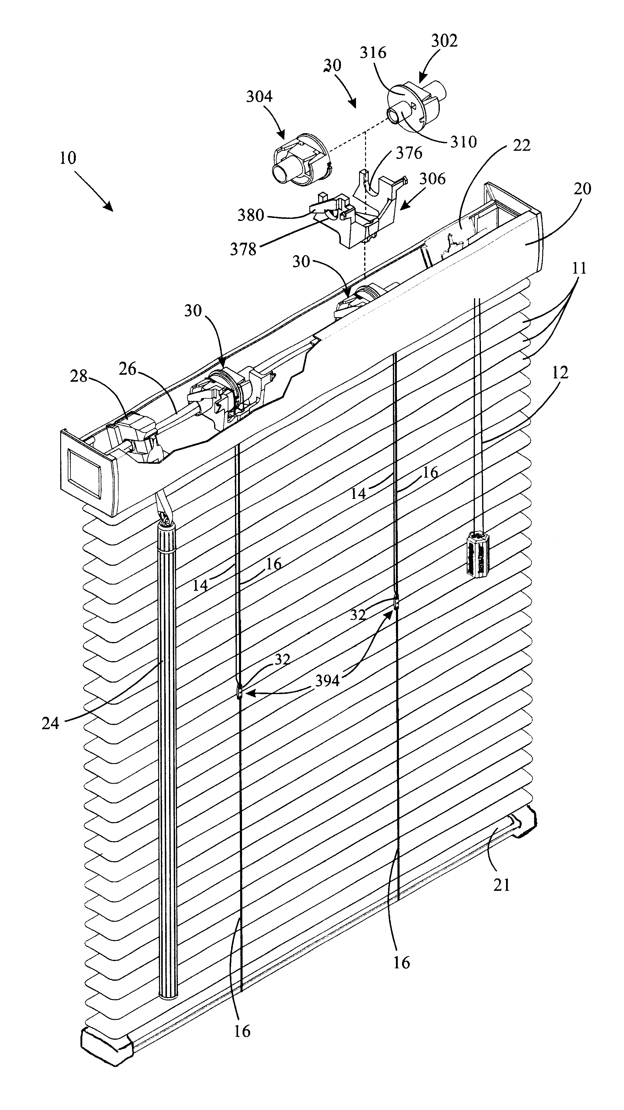
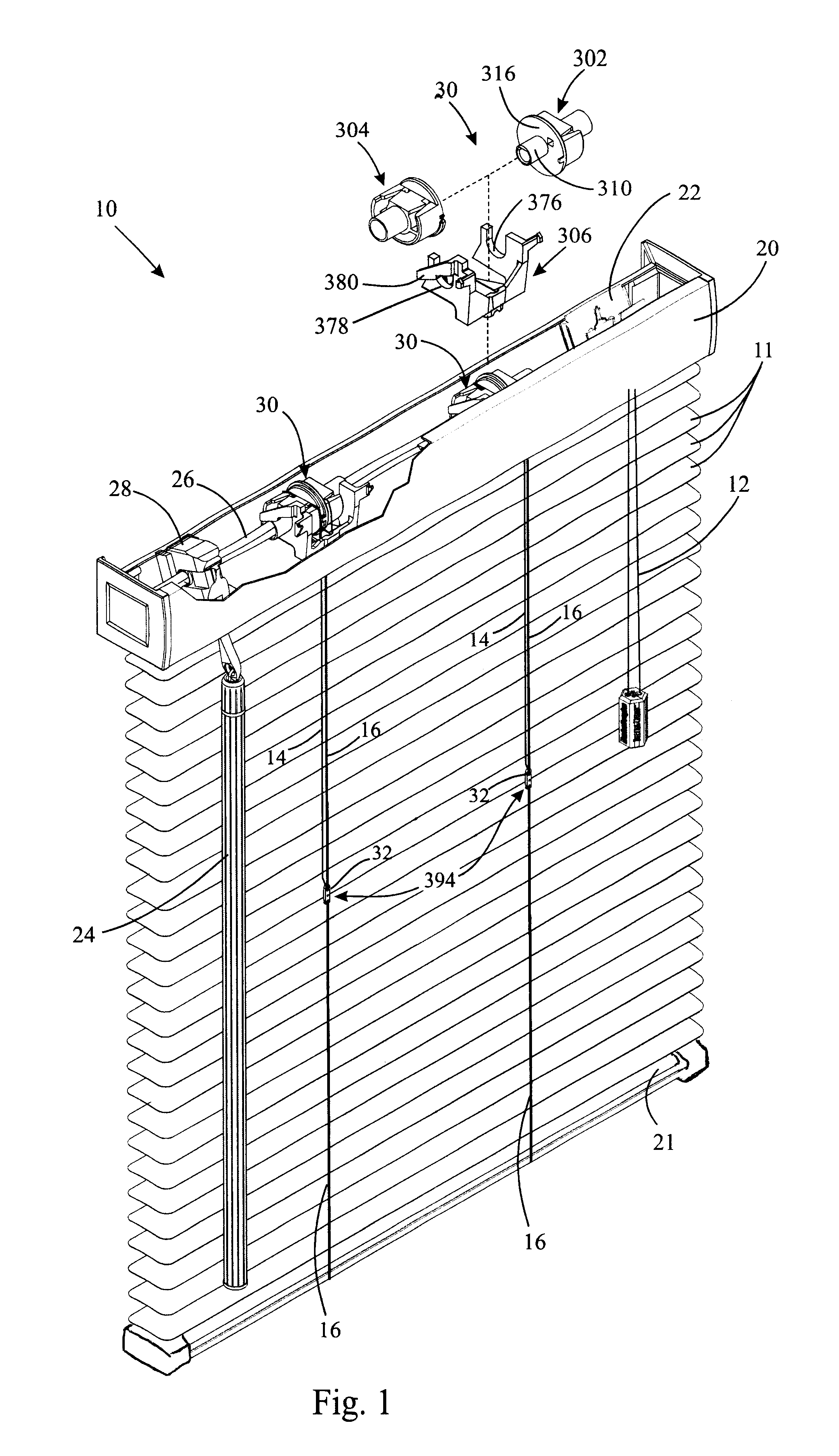
In this second embodiment, the front tilt cable 16A is secured to the head rail 20 (See FIG. 13B), the rear tilt cable 16B is secured to the rear slotted opening 348B of the tape drum 30A and extends only as far as the “break” point 394, where it is terminated. The actuator cord 14B is secured to the front slotted opening 328B and extends all the way to the bottom rail 21. The actuator cord 14B is secured to the bottom rail 21 in a similar manner as the front tilt cable 16A is secured to the bottom rail 21. The actuator cord 14B is also secured to all the ladders 17 supporting the slats 11 located at or below the break point 394 but is not connected to any of the ladders 17 supporting the slats 11 located above the break point 394. So, the actuator cord 14B effectively is one of the tilt cables for the lower portion of the blind.

The lengths of the tilt cables 16A, 16B and of the actuator cord 14B are adjusted so that, when the tape drum 30A is fully rotated clockwise (as seen from t...

fifth embodiment

The projection 322 on the drive drum 302 no longer has to “jump” over the detent on the driven drum 304D, since there is no longer a detent 356 on the driven drum 304D in this As a result, the user no longer experiences a sharp increase in force to engage or disengage the driven drum 304D.

FIGS. 26A, 26B, and 26C depict a sixth embodiment 10E of a blind manufactured in accordance with the present invention. This embodiment 10E is identical in its components to the first embodiment 10 onto the fifth embodiment 10D described above. The difference is that the actuator cord 14 in this sixth embodiment 10E is secured to the rear tilt cable instead of to the front tilt cable. The net effect is that, in one position of the tape drum 30D, when it is rotated fully in the counter-clockwise direction (as seen from the vantage point of FIG. 26C), the actuator cord 14 pulls up on the rear tilt cable 16 at the break point 394, resulting in the lower portion of the blind 30D being closed room side...


PUM


Abstract

A tilter system for a window blind permits a portion of the blind to selectively tilt closed while the balance of the blind remains tilted open. Various arrangements are disclosed for achieving this effect. One includes a lag mechanism in a two-piece tape drum which moves as a single unit during part of its rotation and as two independent drums during the balance of the rotation, with the ladder tape of the blind attached to one of the drums and an actuator cord attached to the other drum. The actuator cord is also anchored to the one of the tilt cables of the ladder tape at a desired point where the selective tilting closed of the blind is to be effected.

Description

BACKGROUND OF THE INVENTIONThe present invention relates to coverings for architectural openings, and, more specifically, to horizontal blinds, such as Venetian blinds, designed to selectively tilt open or tilt closed portions of the blind.Typically, a Venetian blind has a top head rail or other frame member, which both supports the blind and hides the mechanisms used to raise and lower or open and close the blind. The raising and lowering is done by a lift cord attached to the bottom rail (or bottom slat). The slats, which are supported from the head rail, may be allowed to tilt so as to open the blind to allow a maximum of light through the blind, or to close the blind with the room side down (the edge of the slats which is closest to the room is facing down, which means that the other edge of the slats, the edge which is closest to the window or the wall, will be facing up), or to close the blind with the room side up.Tilting the blind closed may be done for the purpose of blocki...

Claims


Application Information

Patent Timeline
Patent Type & Authority Patents(United States)
IPC IPC(8): E06B9/322E06B9/307E06B9/382E06B9/28E06B9/38
CPCE06B9/307E06B9/382E06B9/322E06B2009/285
Inventor ANDERSON, RICHARD N.FISHER, II, ROBERT E.
Owner HUNTER DOUGLAS INC
Why Eureka
Try Eureka