Method of freeing stuck drill pipe

a technology of drill pipe and freeing, which is applied in the direction of fluid removal, sealing/packing, and borehole/well accessories, etc., can solve the problems of over-rig capacity, stuck drill string, and pipe incidents, so as to reduce the amount of force required

Inactive Publication Date: 2005-01-25
SHELL OIL CO
View PDF9 Cites 33 Cited by
  • Summary
  • Abstract
  • Description
  • Claims
  • Application Information

AI Technical Summary

Benefits of technology

In accordance with the foregoing the present invention provides a method for reducing the amount of force necessary to free a stuck drill pipe which comprises an auxiliary method which provides a reduction in the amount of force required to free said pipe.

Problems solved by technology

There are numerous possible causes for the drill string to become stuck during drilling.
Differential sticking, one of the causes for stuck pipe incidents, usually occurs when drilling permeable formations where borehole pressures are greater than formation pressures.
The overpull required to release the pipe may exceed rig capacity, and even cause collapse of the rig.
Often when a drill pipe is differentially stuck the result is that it has to be cut and the target zone cannot be reached by the optimal route.
Such a method could potentially save enormous amounts of time and money in drilling operations.

Method used


Image

  • Method of freeing stuck drill pipe
  • Method of freeing stuck drill pipe
  • Method of freeing stuck drill pipe

Examples


experimental study

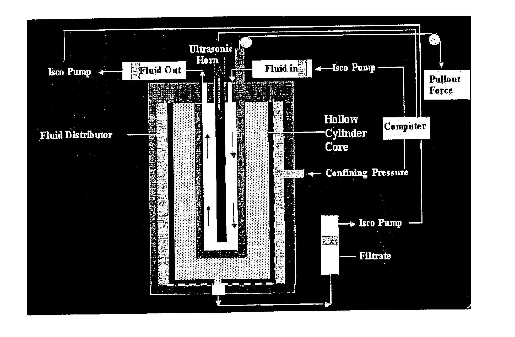
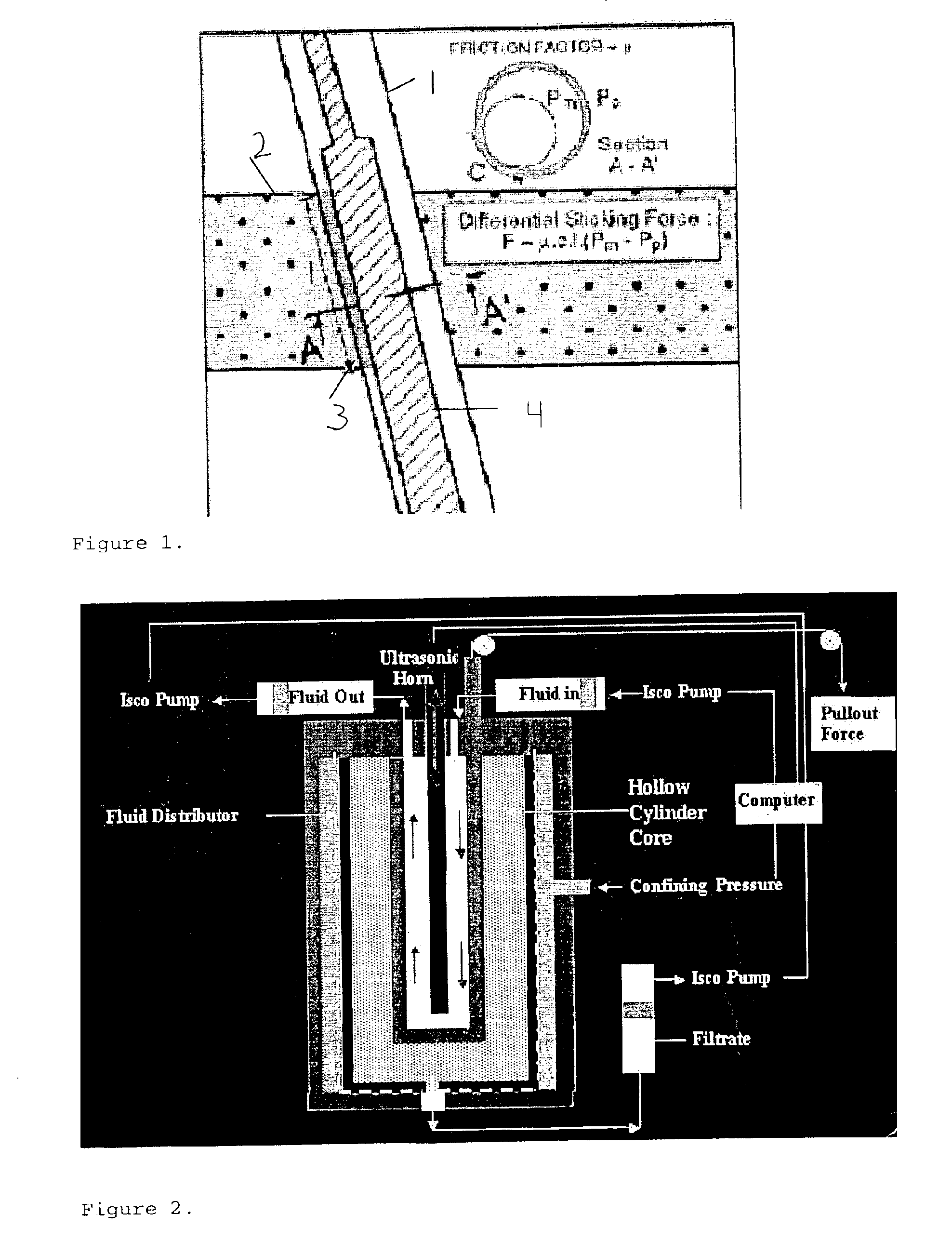
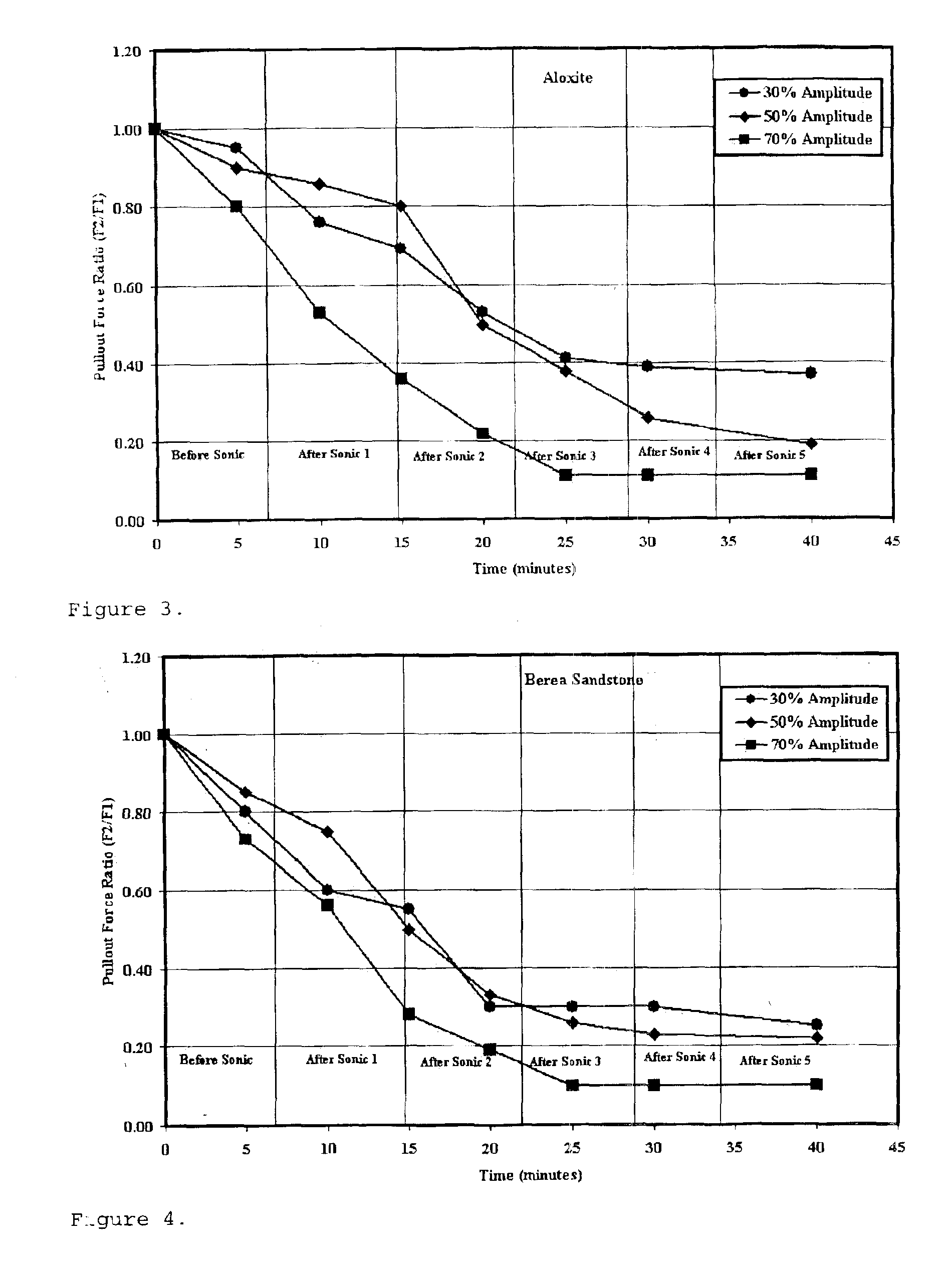
Experiments were designed to demonstrate the usefulness of ultrasonic in reducing pullout force for stuck pipe. A special dynamic hollow cylinder circulation device, described above and shown in FIG. 2 was designed for conducting experiments. The cell pressure, temperature, flow rate, applied horn power and the amplitudes were monitored continuously using data acquisition software. The distance between the damaged surface and the horn was varied to study the effect of distance away from the source.

Again referring to FIG. 2, the system comprises a stainless steel cell, two movable pistons, and an ultrasonic horn holder. It is capable of handling in excess of 5,000 psi pressure and also can be operated at elevated temperature under a specified differential pressure. Two syringe pumps (manufactured by and commercially available from ISCO, Inc. of Nebraska) were used to inject fluid and to control the differential pressure simultaneously with a precision of ±1 psi to measure the permeab...


PUM


Abstract

Disclosed is an auxiliary method for freeing a drill pipe stuck due to build up of filter cake, which provides a reduction in the amount of force required to free said pipe which comprises:a) Lowering an ultrasonic horn type device down the drill pipe to the point of contact between said drill pipe and mud filter cake;b) Producing ultrasonic energy at the point of contact until the contact area is sufficiently reduced such that substantially less force is required to free the pipe.

Description

FIELD OF THE INVENTIONThis invention relates to well servicing and more particularly to a method for the auxiliary use of ultrasonic energy in the case of differential sticking of pipe to reduce the contact area of a filtercake prior to applying freeing force.BACKGROUND OF THE INVENTIONDuring the drilling of oil and gas wells, drilling fluid is circulated through the interior of the drill string and then back up to the surface through the annulus between the drill string and the wall of the borehole. The drilling fluid serves various purposes including lubricating the drill bit and pipe, carrying cuttings from the bottom of the well borehole to the rig surface, and imposing a hydrostatic head on the formation being drilled to prevent the escape of oil, gas, or water into the well borehole during drilling operations.There are numerous possible causes for the drill string to become stuck during drilling. Differential sticking, one of the causes for stuck pipe incidents, usually occurs...

Claims


Application Information

Patent Timeline
Patent Type & Authority Patents(United States)
IPC IPC(8): E21B31/00
CPCE21B31/005
Inventor TUTUNCU, AZRA NURHALE, ARTHUR HERMAN
Owner SHELL OIL CO
Why Eureka
Try Eureka