Liquid discharging method, image forming method, liquid discharge apparatus, and liquid discharge head

a liquid discharge head and liquid discharge technology, applied in printing, inking apparatus, other printing apparatus, etc., can solve the problems of delay the return of the meniscus after discharging, the method is not practical for performing high-speed recording or high-frequency discharging, and the fundamental solution of satellite droplets has not yet been achieved

Inactive Publication Date: 2005-01-25
CANON KK
View PDF19 Cites 8 Cited by
  • Summary
  • Abstract
  • Description
  • Claims
  • Application Information

AI Technical Summary

Benefits of technology

Accordingly, it is an main object of the present invention to provide a novel method for forming droplets capable of operation of a liquid discharge element, i.e., b

Problems solved by technology

However, in this Japanese Laid-Open Patent Applications No. 7-285222, since there is no perception that new satellite droplets further occur after the discharged satellite droplet with a weight equal to that of the main droplet provided, a fundamental solution of satellite droplets has not yet attained.
The above-described patents shows the results wherein satellite droplets are coalesced with a main droplet in midair, but, since each of these results has been acquired by performing plural-time pulse drives for a piezoelectric element, each of these methods is not practical for performing a high-speed recording or a high-frequency discharging because of an elongated driving time.
However, the plural-time deformations for discharge with respect to the piezoelectric element runs counter to the increasing of the driving frequency, and delays the return of the meniscus after discharging to the steady state.
Therefore, this counteracts the improvement in the print speed by a

Method used


Image

  • Liquid discharging method, image forming method, liquid discharge apparatus, and liquid discharge head
  • Liquid discharging method, image forming method, liquid discharge apparatus, and liquid discharge head
  • Liquid discharging method, image forming method, liquid discharge apparatus, and liquid discharge head

Examples


first embodiment

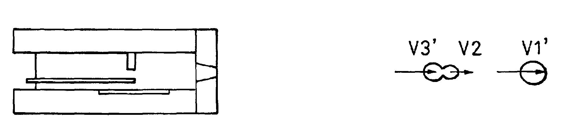
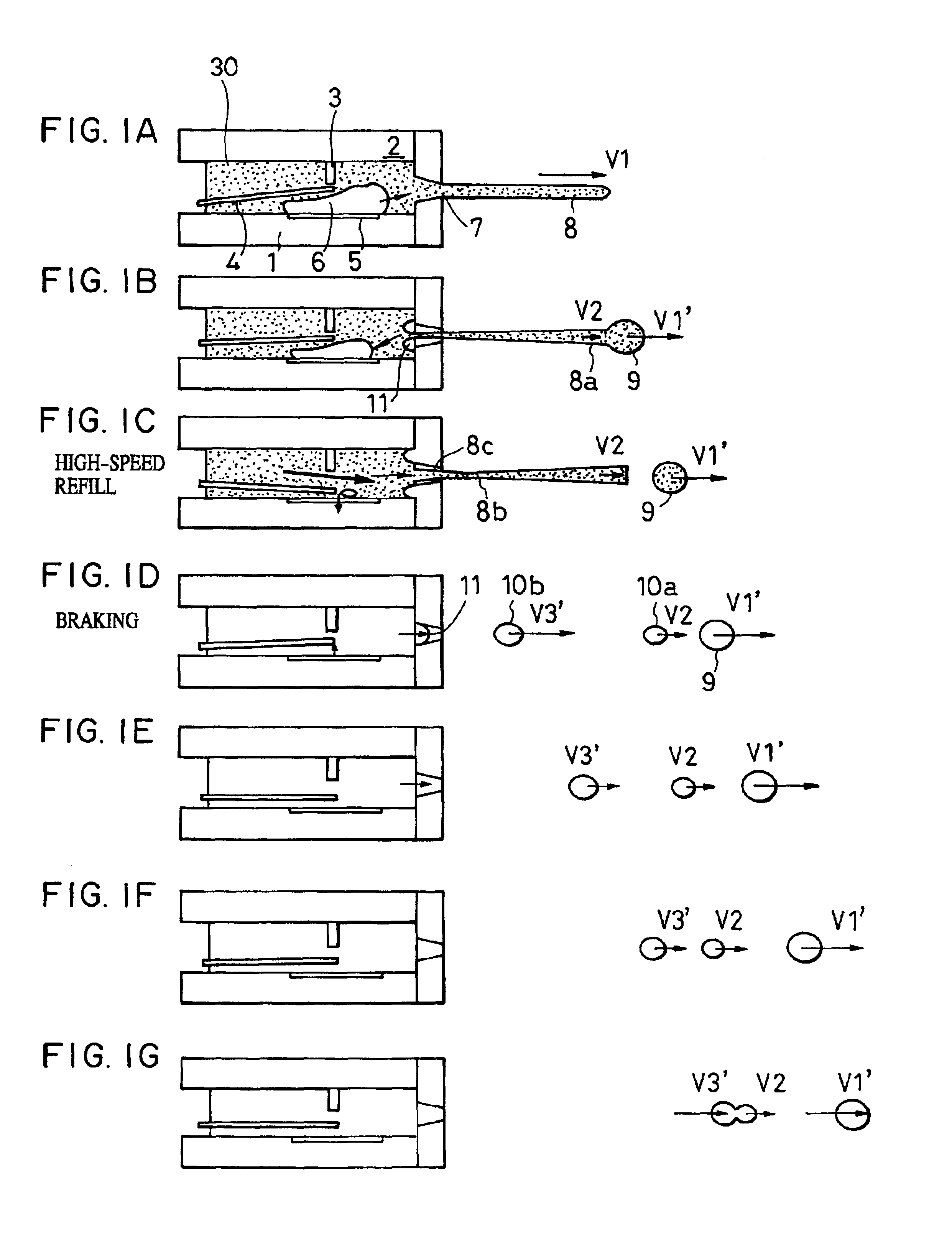
FIGS. 1A to 1G are sectional views taken along the liquid flow path direction of a liquid discharge head in accordance with a first embodiment of the present invention, wherein characteristic phenomena in liquid flow paths are illustrated separately in processes from FIGS. 1A to 1G.

First, a liquid discharge head in accordance with this embodiment will be described.

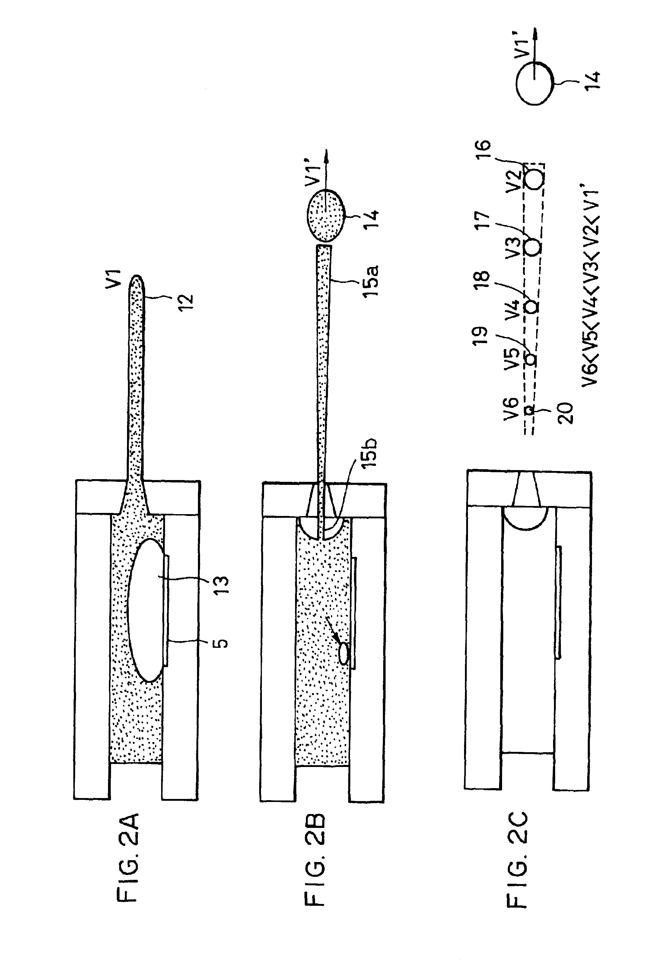
Referring to FIGS. 1A to 1G, in the liquid discharge head as a discharge energy generating element for discharge liquid, a heating unit 5 is provided on a smooth element substrate 1, and liquid flow paths 30 are disposed on the smooth element substrate 1 so as to face the heating unit 5. The liquid flow paths 30 communicates with a discharge port 7, as well as communicates with a common liquid chamber for supplying liquid to a plurality of liquid flow paths 30 on the opposite side of the discharge port 7, and receive from this common liquid chamber the liquid commensurating in the quantity with the liquid discharged from t...

second embodiment

In the above-described first embodiment, description has been made of the configurations of the discharge head wherein an electrothermal transducer is used. FIGS. 3A to 3G shows a discharge head in accordance with a second embodiment of the present invention, wherein a piezoelectric element 40 is used in place of the electrothermal transducer. As can be seen from the figures, when the piezoelectric element 40 is used, two stable dots without mist can be formed, as in the case of the first embodiment.

third and fourth embodiments

In FIGS. 4A to 4H, and FIGS. 5A to 5H, discharge heads in accordance with third and fourth embodiments of the present invention are shown, respectively. The third and fourth embodiments are each modifications of the first embodiment, and their dimensions are identical with each other. FIGS. 4A to 4H, and FIGS. 5A to 5H illustrate the appearances of liquid discharges when a drive voltage is set to 27 V under the dimensional conditions common to the third and fourth embodiments as follows: the area S0 of a discharge port=140 μm2, the size of an electrothermal transducer=18 μm×50 μm, EH=50 μm (EH: the distance from the downstream-side end of the electrothermal transducer to the discharge-port-side end of the element substrate), the size of a movable member=18 μm×190 μm×5 μm (thickness), the gap between the movable member and the electrothermal transducer=4.5 μm, the length of flow path=250 μm, the height of the flow path=50 μm, and the gap between the movable member and a stopper=8 μm....


PUM


Abstract

A liquid discharging method is disclosed for a liquid discharge head which includes a discharge port constituting the portion for discharging liquid, an energy generating element generating the energy for discharging liquid, and liquid flow paths communicating with the discharge port and equipped with the energy generating element, which forms a plurality of droplets by discharging the liquid from the discharge port by the energy of the energy generating element, and which performs recording by shooting the plurality of droplets onto a recording medium. Herein, the plurality of dots is formed of a main droplet which flies at the start; and a droplet formed by coalescing, after capturing, a plurality of satellite droplets which is discharged as a result of the discharge action of the main droplet, before the satellite droplets have been shot onto the recording medium.

Description

BACKGROUND OF THE INVENTION1. Field of the InventionThe present invention relates to on-demand type method and apparatus for discharging liquid, and particularly, to a method and an apparatus or a head for discharging liquid which are capable of using satellite droplet groups in the same manner as a main droplet in an appropriately discharged state, and which achieve a high-speed and high-frequency discharge. The present invention further relates to a liquid discharging method, an image forming apparatus, a liquid discharge apparatus, and a liquid discharge head which can be used for the entire spectrum of the technical field including printers which uses various liquids by bringing them into minute droplets.2. Description of the Related ArtHitherto, conventional arts of forming droplets have been broadly classified into the continuous discharge system and the on-demand system. As disclosed in Japanese Examined Patent Application Publication No. 6-24871, the former system pressurize...

Claims


Application Information

Patent Timeline
IPC IPC(8): B41J2/14B41J2/05B41J2/21
CPCB41J2/14048B41J2/2128B41J2/2107B41J2202/06
Inventor ISHINAGA, HIROYUKIGOTOH, FUMIHIROKATO, MASAOYAMADA, AKITOSHISUGIYAMA, HIROYUKI
Owner CANON KK
Why Eureka
Try Eureka