
Polarization converter, illumination optical device having the polarization converter and projector

a technology of polarization converter and illumination optical device, which is applied in the direction of polarizing elements, instruments, television systems, etc., can solve the problems of deteriorating the light-shielding function of the mask, complicated attachment process of the optical parts housing, etc., and achieves the effect of enhancing the vividness of the image projected, preventing heat damage of the polarization plate, and effective utilization

Inactive Publication Date: 2005-01-25
SEIKO EPSON CORP
View PDF3 Cites 14 Cited by
  • Summary
  • Abstract
  • Description
  • Claims
  • Application Information

AI Technical Summary

Benefits of technology

The present invention provides a polarization converter cable that allows for adjustment of the position between the light-shielding member and the polarization conversion element body in the optical parts housing. This reduces the number of parts and allows for precise positioning of the light-shielding mask. The polarization converter includes a polarizing conversion element body with a plurality of polarization separating films and reflecting films, a light-transmissive member with the polarization separating film and reflecting film, and a plurality of retardation plates. The light-shielding member is attached to the optical parts housing through an adhesive to facilitate adjustment of the position. The invention also provides an illumination optical device, a projector, and a method for effectively utilizing the light beam.

Problems solved by technology

According to the above arrangement, however, relative position between the polarizing conversion element body and the light-shielding mask has to be adjusted as well as the position between the holding frame and the optical parts housing, thus complicating the attachment process in the optical parts housing.
Though it is possible to magnify the aperture ratio of the light-shielding mask for facilitating attachment process, the light-shielding function of the mask is deteriorated.

Method used


Image

  • Polarization converter, illumination optical device having the polarization converter and projector
  • Polarization converter, illumination optical device having the polarization converter and projector
  • Polarization converter, illumination optical device having the polarization converter and projector

Examples


Embodiment Construction

)

An embodiment of the present invention will be descried below with reference to attached drawings.

1. Primary Arrangement of Projector

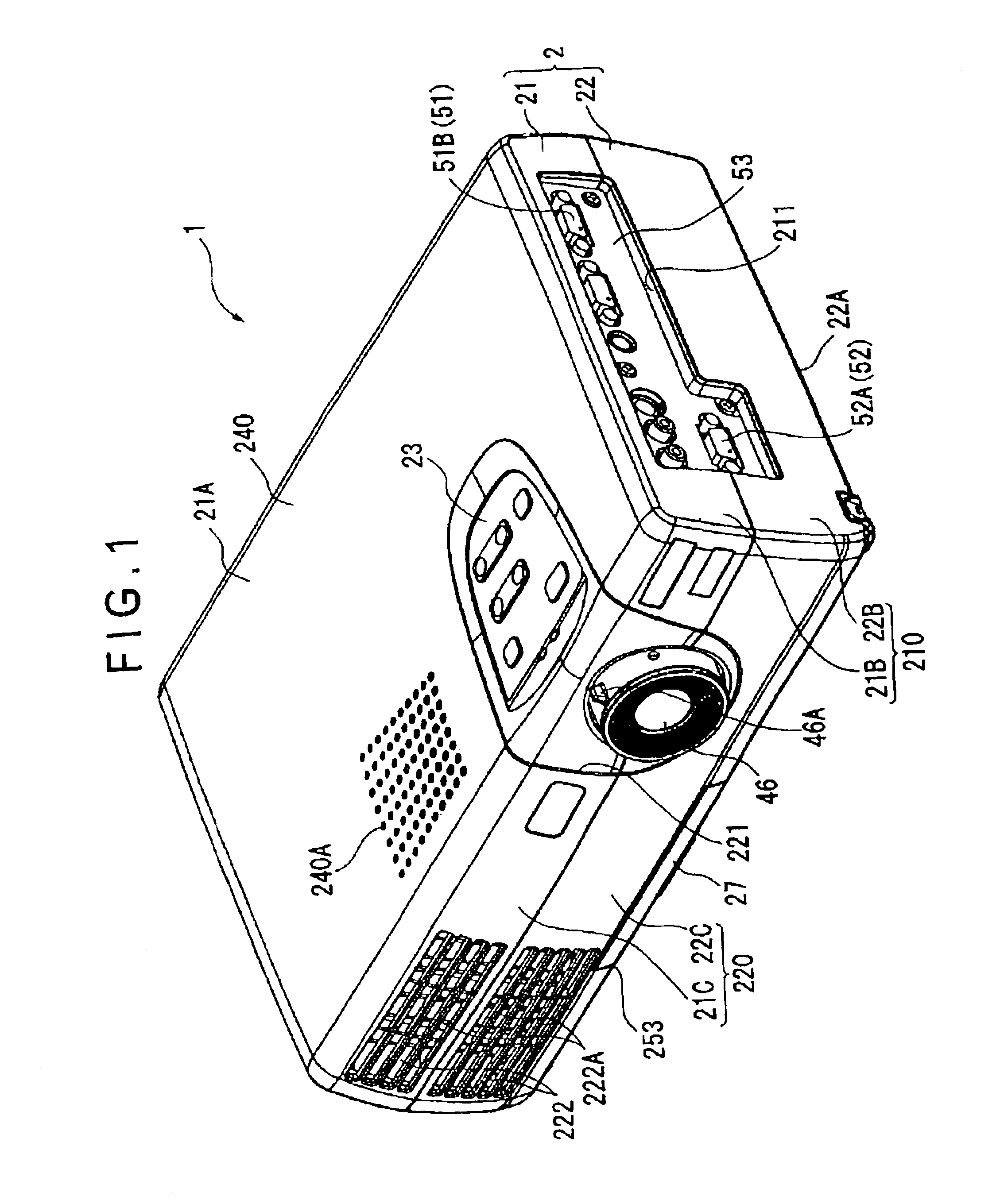
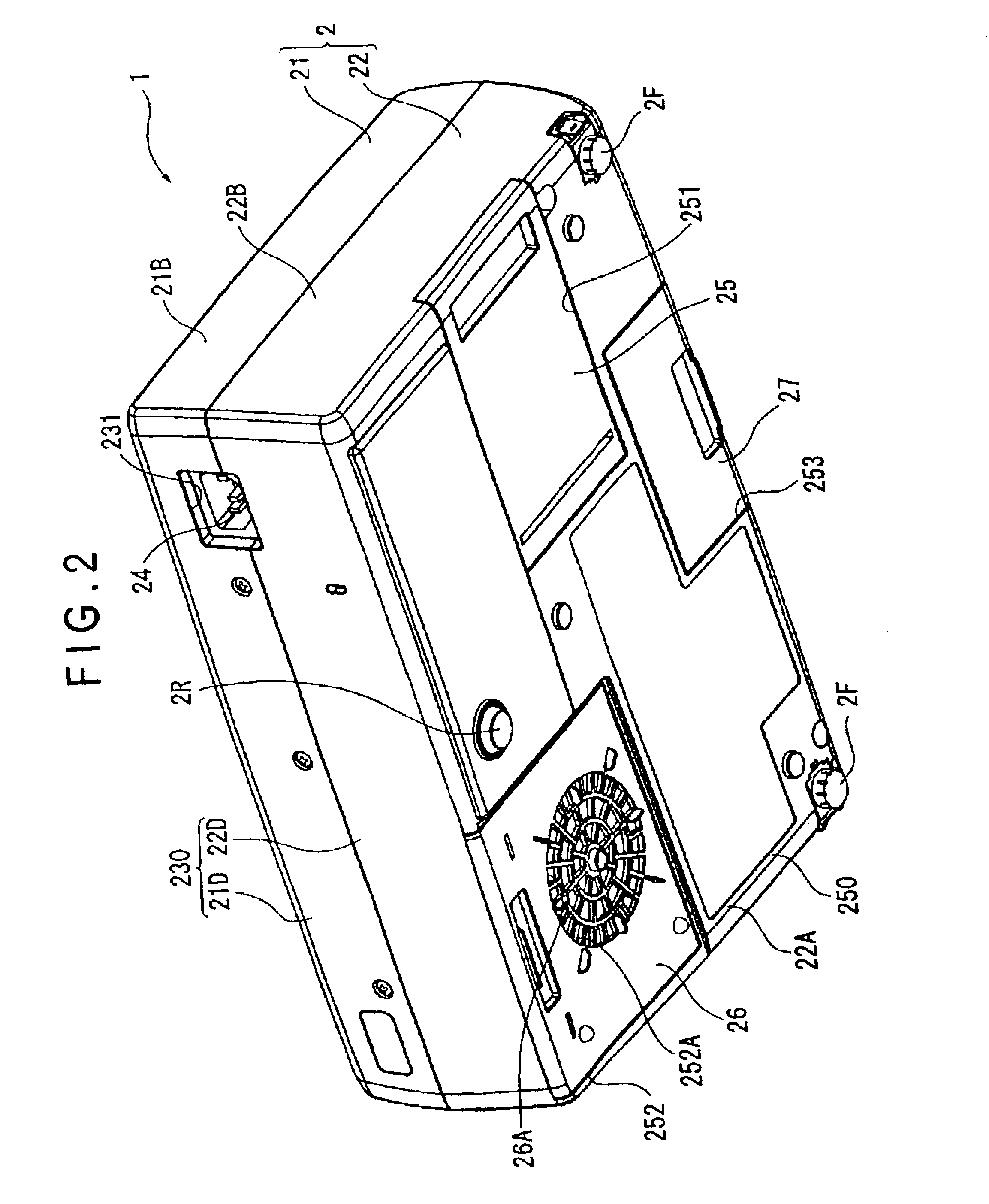
FIG. 1 is a perspective view of a projector 1 seen from upper front side according to an aspect of the present invention. FIG. 2 is a perspective view of the projector 1 seen from lower rear side.

As shown in FIGS. 1 and 2, the projector 1 has an approximately rectangular parallelepiped exterior case 2 made by injection molding. The exterior case 2 is a casing for housing a body of the projector 1, which includes an upper case 21 and a lower case 22, the cases 21 and 22 being attachable and detachable.

As shown in FIGS. 1 and 2, the upper case 21 includes an upper portion 21A, a lateral portion 21B, a front portion 21C and a rear portion 21D respectively constituting the upper side, lateral side, front side and rear side of the projector 1.

In the same manner, the lower case 22 includes a lower portion 22A, a lateral portion 22B, a front portion 22C and ...


PUM

PropertyMeasurementUnit
aspect ratioaaaaaaaaaa
Brewster's angleaaaaaaaaaa
incident angleaaaaaaaaaa

Abstract

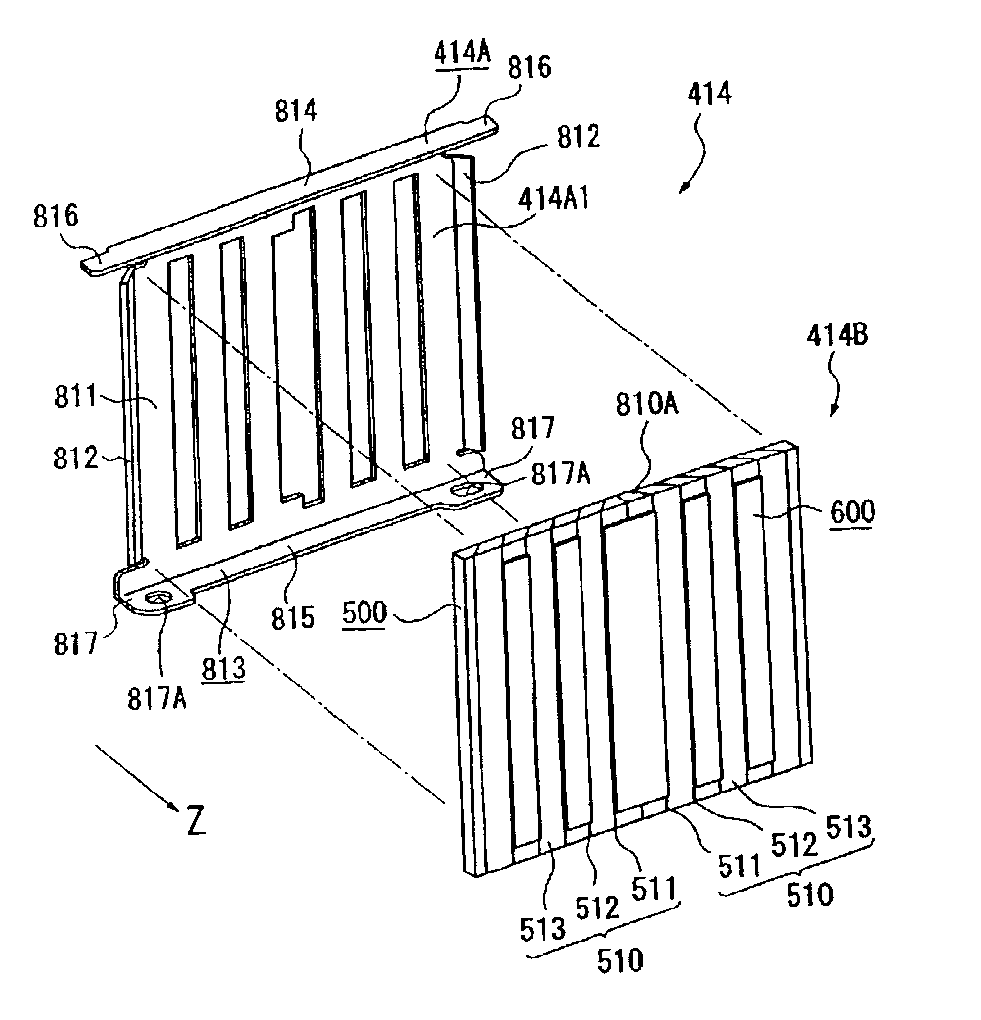
A polarization converter (414) has polarizing conversion element body (414B) including: a polarization separating film (511) that separates an incident light into two linearly polarization beam; a reflecting film (512) alternately disposed between the polarization separating films (511), the reflecting film reflecting a linearly polarization beam reflected by the polarization separating film (511); a sheet glass (513) provided with the polarization separating film (511) and the reflecting film (512); and a retardation plate (600) that converts a polarization axis of the linearly polarization beam transmitted through the polarization separating film (511), a fixing frame (414A) that shields incident light beam on a position on the light-incident side of the polarizing conversion element body (414B) not opposing to the polarizing conversion element body (414B), the fixing frame (414A) having a holder that holds an end of the polarizing conversion element body (414B) and a fixing portion to be fixed to an inner case.

Description

BACKGROUND OF THE INVENTION1. Field of the InventionThe present invention relates to a polarization converter, an illumination optical device having the polarization converter and a projector.2. Description of Related ArtConventionally, a projector has often been used for presentation at a conference, academic society and exhibition. Such projector has a plurality of optical components in a casing, where a light beam irradiated by a light source is enlarged and projected after being modulated to form a projection image. A polarization converter for converting the light beam irradiated by the light source into uniform linearly polarization beam is used for enhancing utilization efficiency of the light beam to obtain a bright projection image.The polarization converter has a polarizing conversion element having a polarization separating film inclined relative to incident light beam to transmit and reflect the light beam from a light source to separate into two linearly polarization be...

Claims


Application Information

Patent Timeline
Patent Type & Authority Patents(United States)
IPC IPC(8): G02B27/28H04N9/31G02F1/13G02B5/30G02F1/1335G03B21/00G03B21/14H04N5/74
CPCG02B27/283G02B27/285H04N9/3105H04N9/3197H04N9/3144H04N9/3167H04N9/3141
Inventor OGAWA, YASUNORIKAWAI, FUMIE
Owner SEIKO EPSON CORP
Learn More