Electro-mechanical surgical device

a surgical device and electromechanical technology, applied in the direction of surgical staples, surgical forceps, incision instruments, etc., can solve the problems of limited number of possible surgical devices identifiable by this system, limited electrical power to the motor, and general torque of motors

Inactive Publication Date: 2005-01-25
TYCO HEALTHCARE GRP LP
View PDF377 Cites 1761 Cited by
  • Summary
  • Abstract
  • Description
  • Claims
  • Application Information

AI Technical Summary

Benefits of technology

The above and other beneficial objects and advantages of the present invention are most effectively attained by providing an electro-mechanical surgical device as described herein. In one example embodiment, an electro-mechanical surgical device includes: a housing; an elongated shaft extending from the housing, a distal end of the elongated shaft being detachably coupleable to a surgical instrument; at least two axially rotatable drive shafts disposed within the elongated shaft, a distal end of each of the drive shafts being configured to couple with the surgical instrument; a steering cable arrangement being configured to steer the distal end of the elongated shaft; and a motor system disposed within the housing and configured to drive the drive shafts and the steering cable arrangement.
In another example embodiment, the electro-mechanical surgical device includes a control system and a remote control unit configured to communicat

Problems solved by technology

The number of possible surgical devices identifiable by this system is limited to the four possible combination of up to two magnets.
Due to size considerations, these motors generally provide limited torque.
Such battery systems, however, provide limited electrical power to the motors, further limiting the torque output by the motors.
In addition, it is generally not possible to accurately

Method used


Image

  • Electro-mechanical surgical device
  • Electro-mechanical surgical device
  • Electro-mechanical surgical device

Examples


Embodiment Construction

Those skilled in the art will gain an appreciation of the present invention from a reading of the following description when viewed in conjunction with the accompanying drawings of FIGS. 1-16, inclusive. The individual reference characters designate the same or similar elements throughout the several views.

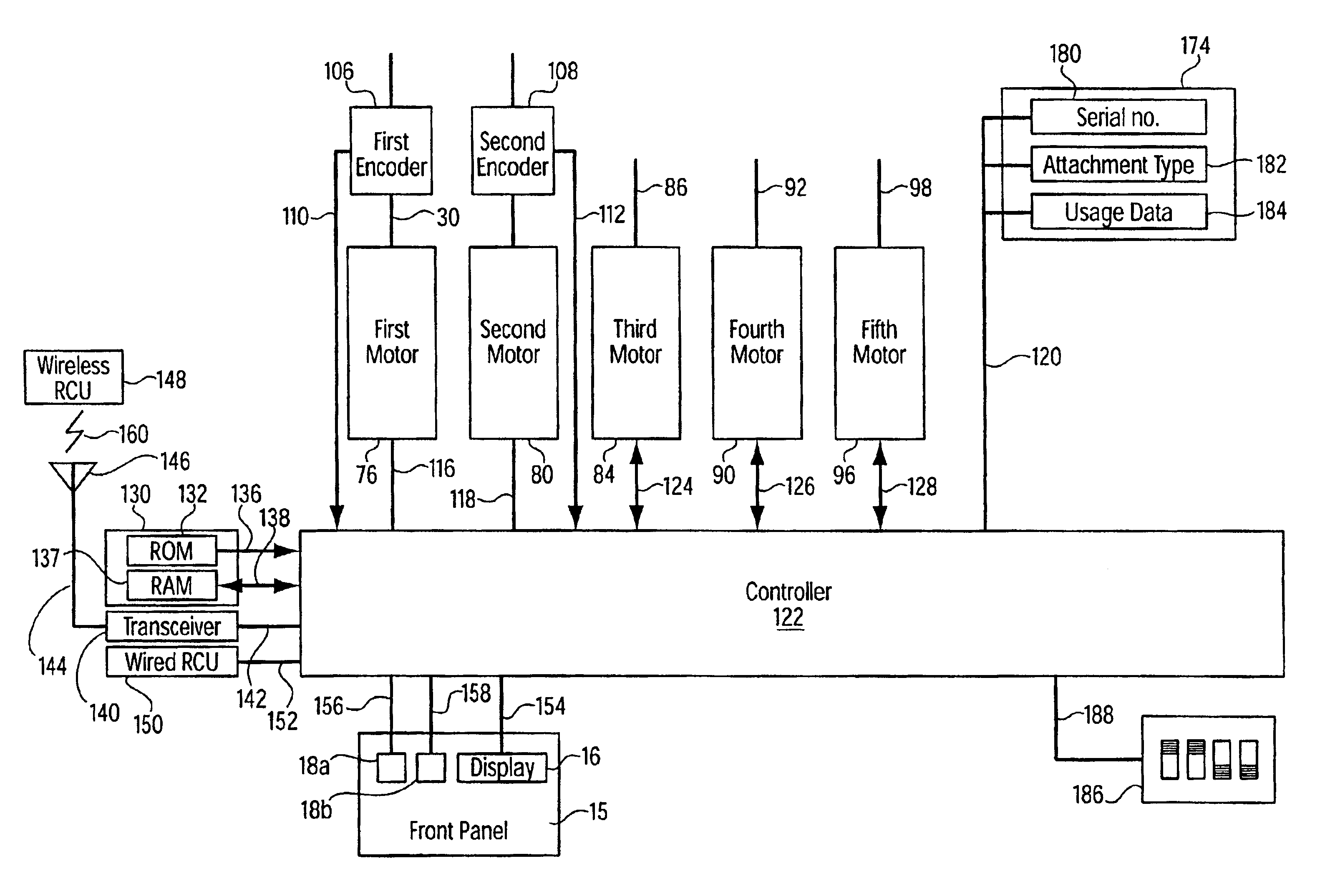
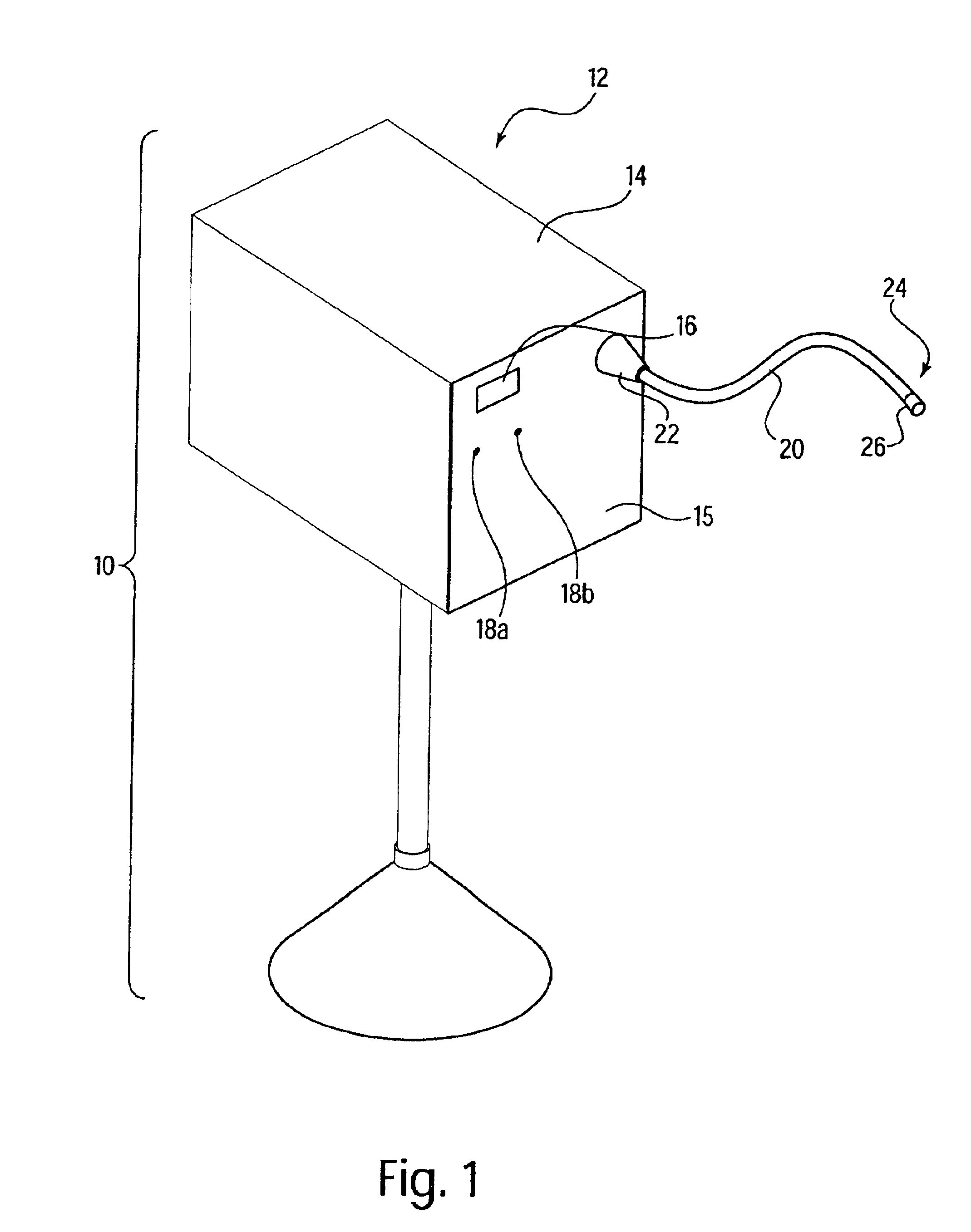
Referring to FIG. 1, there is seen a perspective view of an electro-mechanical surgical device 10 according to an example embodiment of the present invention. Electro-mechanical surgical device 10 may include, for example, a remote power console 12, which includes a housing 14 having a front panel 15. Mounted on front panel 15 are a display device 16 and indicators 18a, 18b, which are more fully described hereinbelow. A flexible shaft 20 may extend from housing 14 and may be detachably secured thereto via a first coupling 22. The distal end 24 of flexible shaft 20 may include a second coupling 26 adapted to detachably secure a surgical instrument or attachment to the distal end 24...


PUM


Abstract

An electro-mechanical surgical device includes: a housing; an elongated shaft extending from the housing, a distal end of the elongated shaft being detachably coupleable to a surgical instrument; at least two axially rotatable drive shafts disposed within the elongated shaft, a distal end of each of the drive shafts being configured to couple with the surgical instrument; a steering cable arrangement, the steering cable arrangement being configured to steer the distal end of the elongated shaft; and a motor system disposed within the housing, the motor system being configured to drive the drive shafts and the steering cable arrangement. A control system may be provided for controlling the motor system. A remote control unit may also be provided for controlling the motor system via the control system. Sensors, such as optical or Hall-effect devices, may be provided for determining the position of the elements of the surgical instrument based on the detected rotation of the drive shafts. A memory unit stores a plurality of operating programs or algorithms, each corresponding to a type of surgical instrument attachable to the electro-mechanical surgical device. The control system reads or selects from the plurality of operating programs or algorithms, the operating program or algorithm corresponding to the type of surgical instrument attached to the electro-mechanical surgical device.

Description

FIELD OF THE INVENTIONThe present invention relates to an electro-mechanical surgical device.BACKGROUND INFORMATIONThe literature is replete with descriptions of surgical devices. For example, U.S. Pat. No. 4,705,038 to Sjostrom et al. describes a surgical system for powered instruments. The system includes a handpiece containing a motor and including a recess adapted to receive one of a plurality of surgical devices. A pair of reed switches is disposed within the recess, and each of the surgical devices includes one or two magnets adapted to actuate the reed switches in a particular combination when the device is assembled with the handpiece. The combination of reed switches activated by the magnets of the assembled handpiece and surgical device identifies to the system the surgical device so assembled with the handpiece. The number of possible surgical devices identifiable by this system is limited to the four possible combination of up to two magnets.U.S. Pat. No. 4,995,877 to Am...

Claims


Application Information

Patent Timeline
IPC IPC(8): A61B17/11A61B17/115A61B10/00A61B17/03A61B17/068A61B17/072A61B17/00A61B17/28A61B17/32A61B19/00A61B10/02
CPCA61B10/0233A61B17/072A61B17/07207A61B17/1114A61B17/115A61B17/00A61B2019/2242A61B17/00491A61B17/11A61B19/2203A61B2010/0208A61B2017/00022A61B2017/00039A61B2017/00199A61B2017/003A61B2017/00323A61B2017/00398A61B2017/00464A61B2017/00473A61B2017/00482A61B2017/00734A61B2017/07214A61B2017/0725A61B2017/07271A61B2017/2905A61B2017/2943A61B2017/320052A61B2017/32113A61B34/30A61B34/71A61B2034/2059A61B17/00234A61B17/068A61B34/20A61B2017/2927A61B2034/301
Inventor WHITMAN, MICHAEL P.BURBANK, JOHN E.ZEICHNER, DAVID A.
Owner TYCO HEALTHCARE GRP LP
Why Eureka
Try Eureka