Condensation evacuating window sill

a technology of condensation and window sills, applied in the direction of glass pane fixing, building components, construction, etc., can solve the problems of imprégnation of wood, allergies and other health hazards, and achieve the effects of preventing deterioration, improving the overall aesthetic appearance of the window, and being easily manufactured

Inactive Publication Date: 2005-02-01
LAPIERRE NORMAND
View PDF8 Cites 38 Cited by
  • Summary
  • Abstract
  • Description
  • Claims
  • Application Information

AI Technical Summary

Benefits of technology

Also, the proposed structure is designed so as to be complimentary or of a pleasing appearance so as to prevent deterioration and even improve on the overall aesthetical appearance of the window and associated window frame. Still furthermore, the proposed structure is designed so as to be easily manufacturable through conventional manufacturing processes such as extrusion so as to provide a structure that will be economically feasible, long lasting and relatively trouble free in operation.

Problems solved by technology

When the condensation accumulating on a glass surface of a window flows downwardly upon the adjacent window sill, it eventually impregnates the wood leading to rotting of the latter.
The presence of mildew and molds can potentially lead to allergies and other health hazards.
The condensate also sometimes comes into contact with draperies or curtains covering a window causing staining and further mildew.
The device however requires periodic attention to discharge the accumulated condensation within the receptacle.
Also, it has been known to deter the overall aesthetical aspect of the window frame.

Method used


Image

  • Condensation evacuating window sill
  • Condensation evacuating window sill
  • Condensation evacuating window sill

Examples


Embodiment Construction

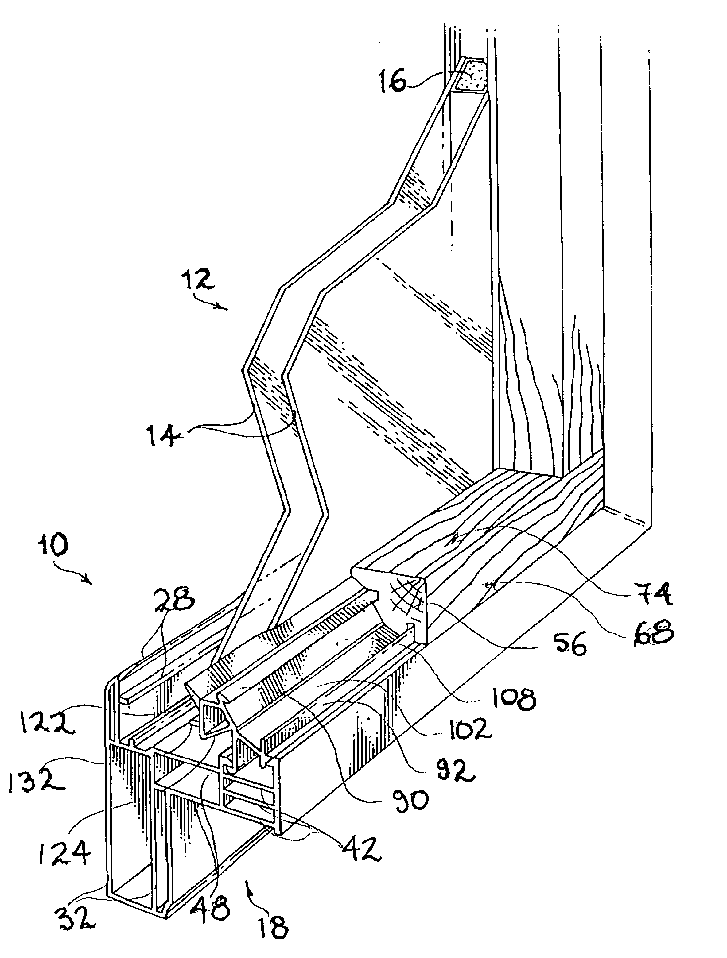
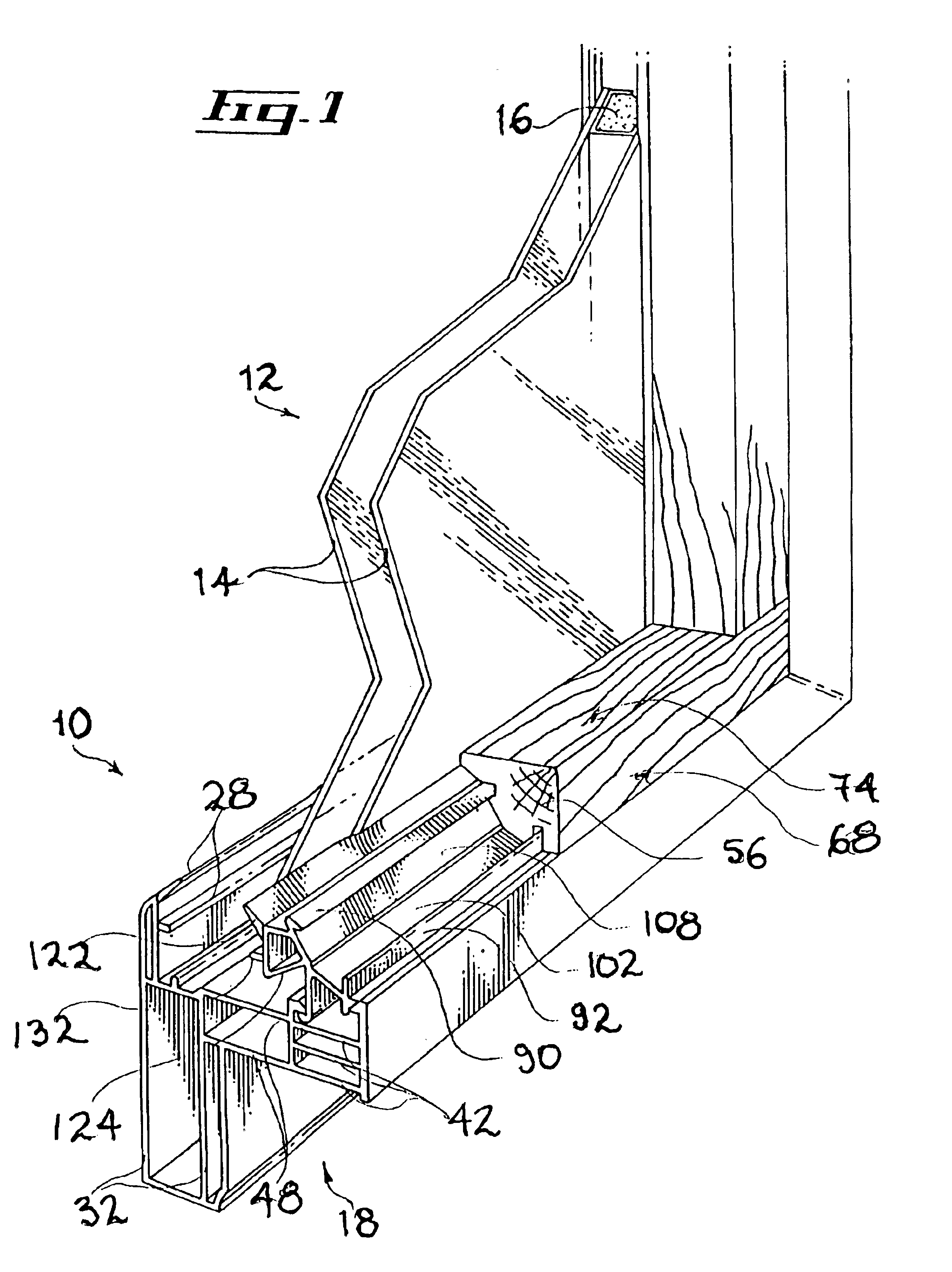
Referring to FIG. 1, there is shown a condensation evacuating window sill 10 in accordance with an embodiment of the present invention. The window sill 10 is shown mounted adjacent a conventional double pane-type window 12 including a pair of glass panes 14 maintained in a substantially parallel and spaced relationship relative to each other by a conventional pane peripheral insulating and spacing component 16.

Both the window sill 10 and the window 12 are shown mounted to a conventional window frame 18. It should, however, be understood that the window sill 10 could be used in other contexts such: as with other types of windows and / or other types of window frames without departing from the scope of the present invention.

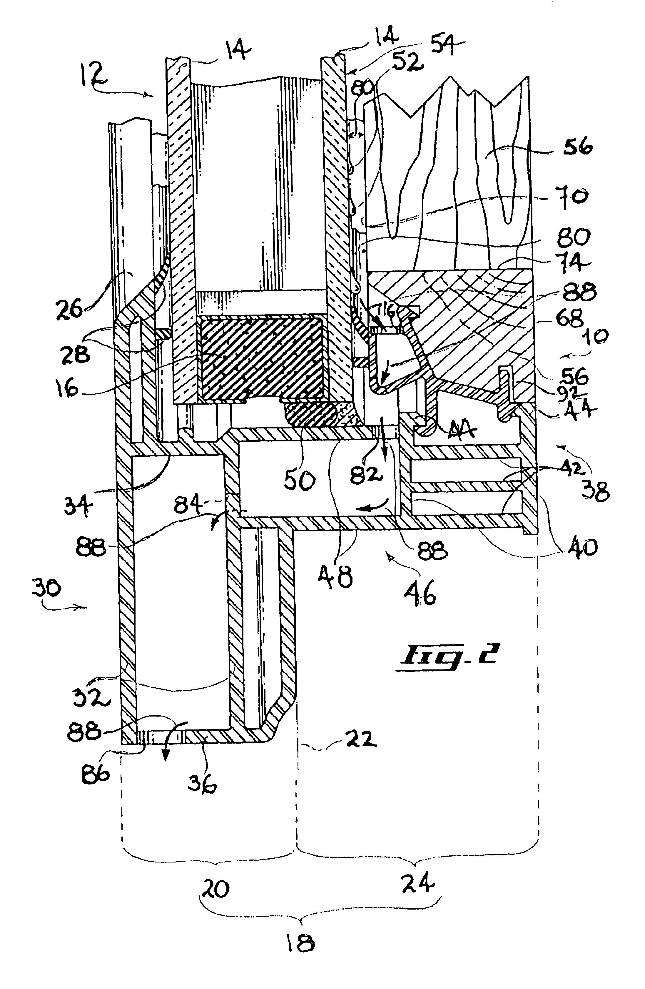
As shown more specifically in FIG. 2, the window frame 18 typically includes a frame exterior portion 20 adapted to be positioned outside relative to a reference line 22 schematically representing the exterior surface of a building wall (not shown). The window frame ...


PUM

PropertyMeasurementUnit
moldingaaaaaaaaaa
relative displacementaaaaaaaaaa
surface temperatureaaaaaaaaaa

Abstract

A condensation evacuating sill for evacuating condensate having formed on an inner surface of a window pane includes a molding strip and an attachment extrusion for attaching the molding strip to the window frame. The attachment extrusion includes an extrusion-to-molding attachment section for attaching the molding attachment surface to the attachment extrusion and an extrusion-to-frame attachment section for attaching the attachment extrusion to the window frame. The attachment extrusion is configured and sized for attaching the molding strip to the window frame so that the molding inner edge is spaced relative to the inner surface by a pane-to-molding spacing allowing the condensate to flow therethrough without contacting the molding strip. The attachment extrusion further includes flow guiding components for guiding the flow of condensate from the pane-to-molding spacing to a discharge location located away from the attachment extrusion.

Description

The present invention relates to the general field of window accessories and is particularly concerned with a condensation evacuating window sill.BACKGROUND OF THE INVENTIONWater vapor is normally present in a gaseous state in the rooms of buildings. The water vapor forms as liquid condensation upon contact with the interior surfaces of a room having a surface temperature sufficiently cool to allow the vapor to transform in its liquid state.Typically, the condensation appears during the colder winter months when the warm and moist air inside the building strikes the colder glass surfaces of doors and windows chilled by the outside air. The condensate forming on the glass surfaces of doors and windows accumulates on the interior surface of the glass. The condensate then flows downward under the action of gravity. Eventually, the condensate reaches the window sill.There exists a current trend towards so-called “cocooning” when individuals spend a greater amount of time indoors and mor...

Claims


Application Information

Patent Timeline
Patent Type & Authority Patents(United States)
IPC IPC(8): E06B3/58E06B7/14E06B3/30
CPCE06B7/14E06B3/5821E06B3/303
Inventor LAPIERRE, NORMAND
Owner LAPIERRE NORMAND
Why Eureka
Try Eureka