

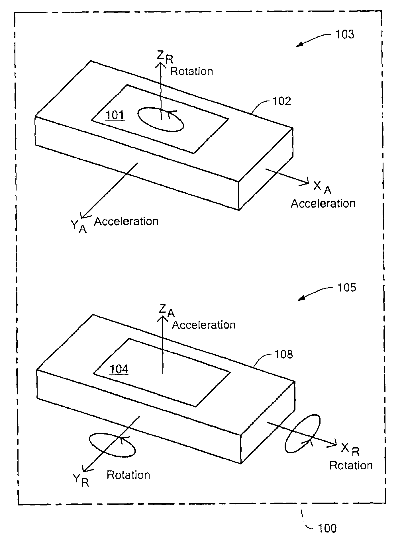
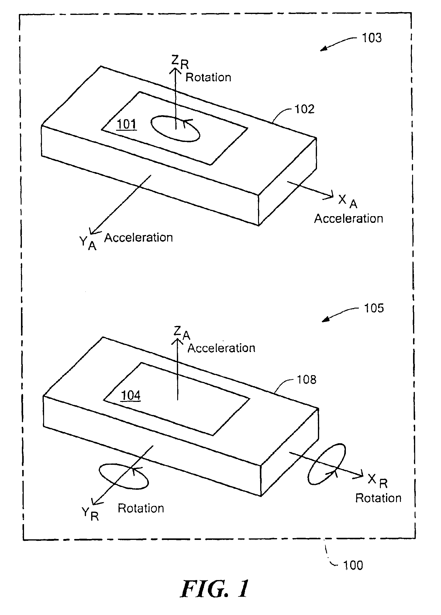
Six degree-of-freedom micro-machined multi-sensor
a micro-machined multi-sensor, free-range technology, applied in the direction of acceleration measurement in multiple dimensions, turn-sensitive devices, instruments, etc., can solve the problems of providing only 1-axis of acceleration sensing, providing only 1-axis of angular rate sensing, and providing no acceleration sensing information
- Summary
- Abstract
- Description
- Claims
- Application Information
AI Technical Summary
Benefits of technology
Problems solved by technology
Method used
Image

Examples
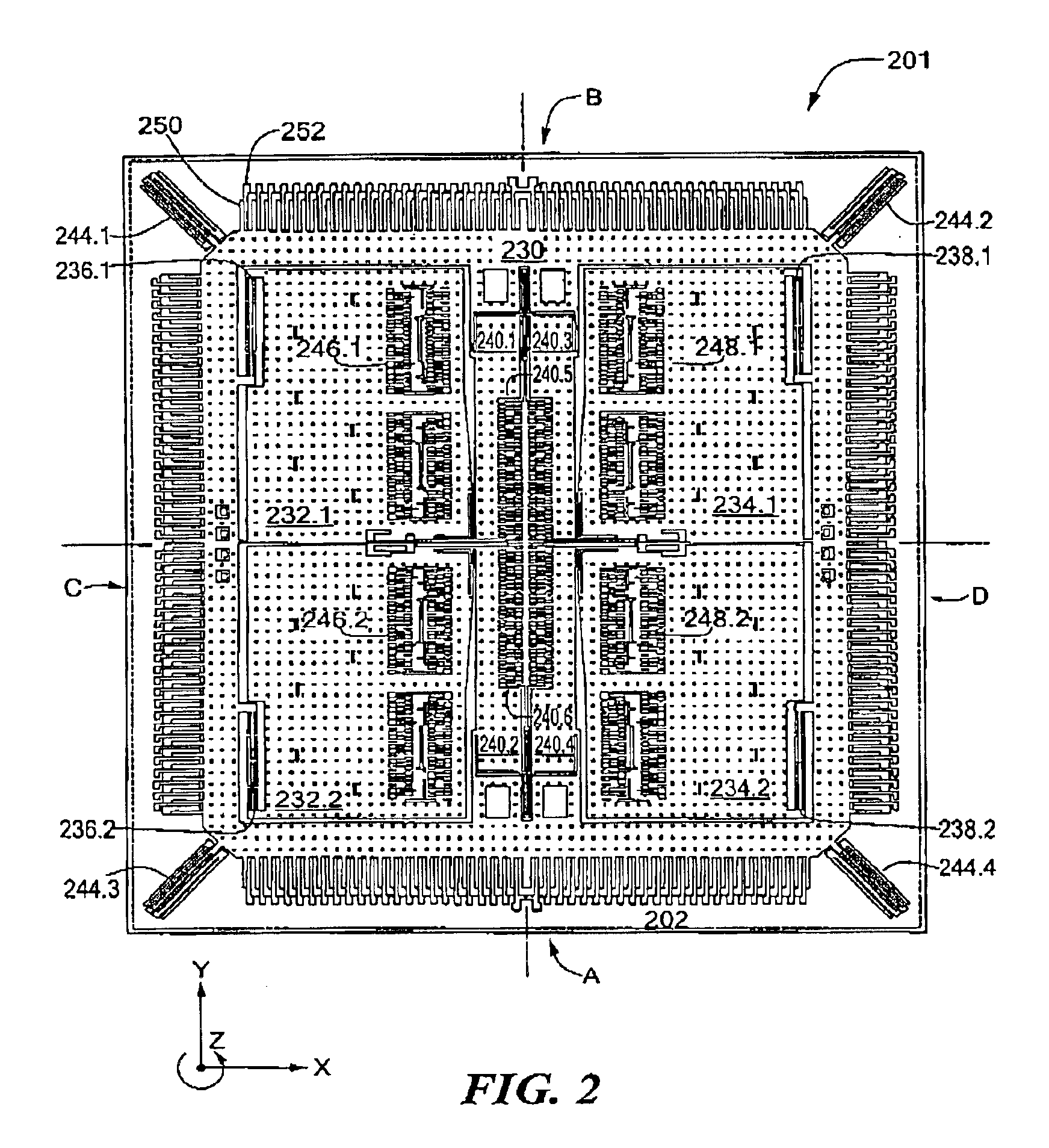
embodiment 201
FIG. 2 depicts an illustrative embodiment 201 of the sensor 101 included in the MEMS substructure 103 (see FIG. 1). In the illustrated embodiment, the sensor 201 includes a rigid accelerometer frame 230, and proof masses 232.1-232.2 and 234.1-234.2, formed on a substrate 202. The proof masses 232.1-232.2 are suspended from the rigid frame 230 by resonator flexures 236.1-236.2, respectively, and the proof masses 234.1-234.2 are suspended from the rigid frame by resonator flexures 238.1-238.2, respectively. Moreover, the rigid frame 230 is anchored to the substrate by accelerometer flexures 244.1-244.4, which are diagonally disposed on the substrate 202.
The sensor 201 further includes drive electrode structures 246.1-246.2 and 248.1-248.2, and acceleration sense electrode structures A-D. As shown in FIG. 2, the drive electrode structures 246.1-246.2 and 248.1-248.2 include respective pluralities of drive electrodes (“fingers”), which are parallel to and interdigitated with one another...
embodiment 303
FIG. 3 depicts a schematic diagram of an illustrative embodiment 303 of the MEMS substructure 103 of FIG. 1. In the illustrated embodiment, the MEMS substructure 303 includes a sensor 301, a transresistance amplifier 304, a plurality of difference amplifiers 306, 308, 310, 312, 316, and 320, a plurality of summing amplifiers 314, 318, and 322, and a phase demodulator 324. As described above, the proof masses 232.1-232.2 (see FIG. 2) are coupled together to move as a single mass, and the proof masses 234.1-234.2. (see FIG. 2) are similarly coupled together to move as a single mass. Accordingly, the sensor 301 includes a rigid accelerometer frame 330 representing the rigid frame 230 (see FIG. 2), a first proof mass 332 representing the proof masses 232.1-232.2, and a second proof mass 334 representing the proof masses 234.1-234.2.
Specifically, the first proof mass 332 is suspended from the rigid frame 330 by resonator flexures 336, which are representative of the flexures 236.1-236.2 ...
PUM
 Abstract
Description
Claims
Application Information