Accumulation type fuel injection system

a fuel injection system and accumulation technology, applied in the direction of liquid fuel feeders, fuel injecting pumps, machines/engines, etc., can solve the problems of difficult to achieve the perpendicularity between the innermost surface of the female thread and the perpendicularity of the female thread, increase the production cost of the process such as the threading process of the threaded portion through a forging process or a cutting process, etc., to achieve the effect of improving sealing performance, reducing the cost of reducing

Inactive Publication Date: 2005-02-01
DENSO CORP
View PDF7 Cites 10 Cited by
  • Summary
  • Abstract
  • Description
  • Claims
  • Application Information

AI Technical Summary

Benefits of technology

It is therefore an object of the present invention to provide an accumulation type fuel injection system, which is formed in inexpensive structure and is capable of improving high-pressure sealing performance.
It is another object of the present invention to provide an accumulation type fuel injection system having an accumulation device, which has an accessory portion corresponding to a safety device and supplies accumulated high-pressure fuel though the accessory portion, so that the accumulation type fuel injection system is formed in inexpensive structure and is capable of improving high-pressure sealing performance.
Accordingly, even in the case where the inclination of the central axis of the threaded portion is deviated, a fastening force generated by the thread connection can be applied to the connection object stably through the sealing member having the spherical surface. Therefore, variation in processing accuracy is permitted, so inexpensive structure is achieved. Sealing performance can be improved by employing the connection structure for connecting the accessory portion to the connection object in thread connection through the sealing member having the spherical surface.

Problems solved by technology

However, production cost of process such as a threading process of the threaded portion through a forging process or a cutting process is increased.
Specifically, compared to the processing of an external surface, the processing accuracy in the perpendicularity between a female thread and the innermost surface is difficult to achieve in the case where the female thread, or an internal surface, is processed.

Method used


Image

  • Accumulation type fuel injection system
  • Accumulation type fuel injection system
  • Accumulation type fuel injection system

Examples


Embodiment Construction

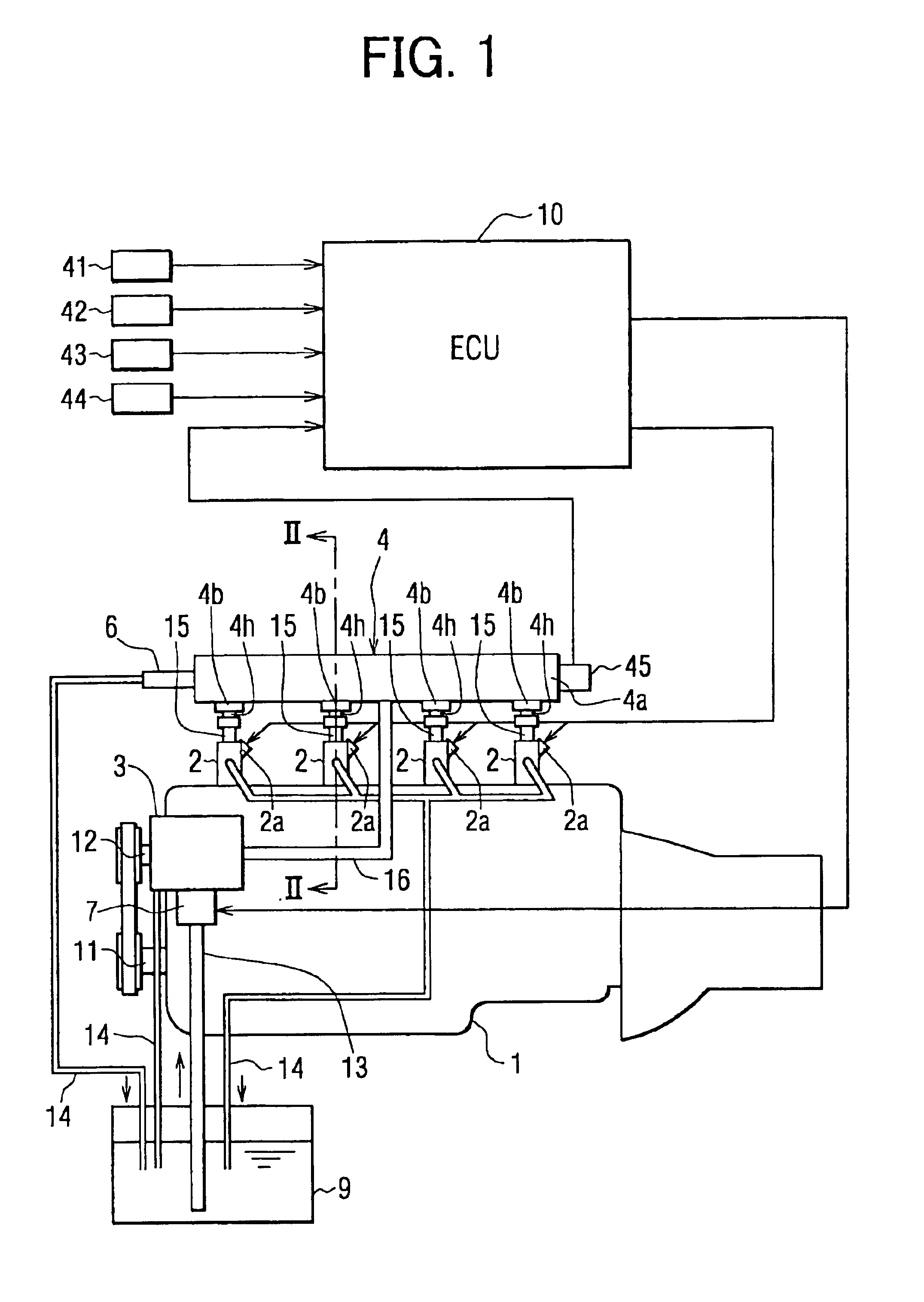
Referring to FIG. 1, a common rail type fuel injection system as an accumulation type fuel injection system of the present embodiment of the present invention is illustrated. The common rail type fuel injection system in FIG. 1 is mounted to a diesel engine.

As shown in FIG. 1, the common rail type fuel injection system has a plurality of (four, in the present embodiment) injectors 2, a high-pressure supply pump 3, a common rail 4, and an electronic control unit (an ECU) 10. The injectors 2 are mounted to respective cylinders of a multi-cylinder internal combustion engine (a multi-cylinder engine) 1 such as a multi-cylinder diesel engine. The high-pressure supply pump 3 is driven by the multi-cylinder engine 1 to rotate. The common rail 4 functions as the accumulation device for accumulating the high-pressure fuel discharged from the high-pressure supply pump 3. The ECU 10 electronically controls the plurality of injectors 2. The ECU 10 is a control device for controlling the engine ...


PUM


Abstract

A common rail of an accumulation type fuel injection system has a common rail main body, distributing portions and accessory portions. The common rail main body provides an accumulation chamber for accumulating high-pressure fuel discharged from a high-pressure supply pump. The distributing portion can be connected with a pressure introduction pipe for introducing the accumulated high-pressure fuel to an injector mounted to a cylinder. The accessory portion is disposed on a fuel outlet side of the distributing portion and is connected with the distributing portion and the high-pressure pipe in thread connection. The accessory portion has a sealing member between the accessory portion and a connection object on the distributing portion side. The sealing member has a sealing surface formed substantially in the shape of a spherical surface on the connection object side.

Description

CROSS REFERENCE TO RELATED APPLICATIONThis application is based on and incorporates herein by reference Japanese Patent Application No. 2002-332703 filed on Nov. 15, 2002.BACKGROUND OF THE INVENTION1. Field of the InventionThe present invention relates to an accumulation type fuel injection system, in particular to sealing structure of an accumulation device of the accumulation type fuel injection system.2. Description of Related ArtAs one of accumulation type fuel injection systems, a common rail type fuel injection system for a diesel engine having a high-pressure supply pump and a common rail is known, for instance. The high-pressure supply pump is rotated by a crankshaft of the diesel engine so that the supply pump pressurizes fuel drawn from a fuel tank and discharges the high-pressure fuel. The common rail functions as a kind of surge tank for accumulating the high-pressure fuel discharged from the high-pressure supply pump.The fuel is accumulated in the common rail at a relat...

Claims


Application Information

Patent Timeline
Patent Type & Authority Patents(United States)
IPC IPC(8): F02M63/02F02M55/02F02M63/00F02M55/00F02M59/46
CPCF02M55/005F02M63/0215F02M55/025F02M63/0205
Inventor WATANABE, TOSHIKAZU
Owner DENSO CORP
Why Eureka
Try Eureka