

Tool belt with spaced receiver blocks selectively receiving both complimentary tool holders and tools
- Summary
- Abstract
- Description
- Claims
- Application Information
AI Technical Summary
Benefits of technology
Problems solved by technology
Method used
Image

Examples
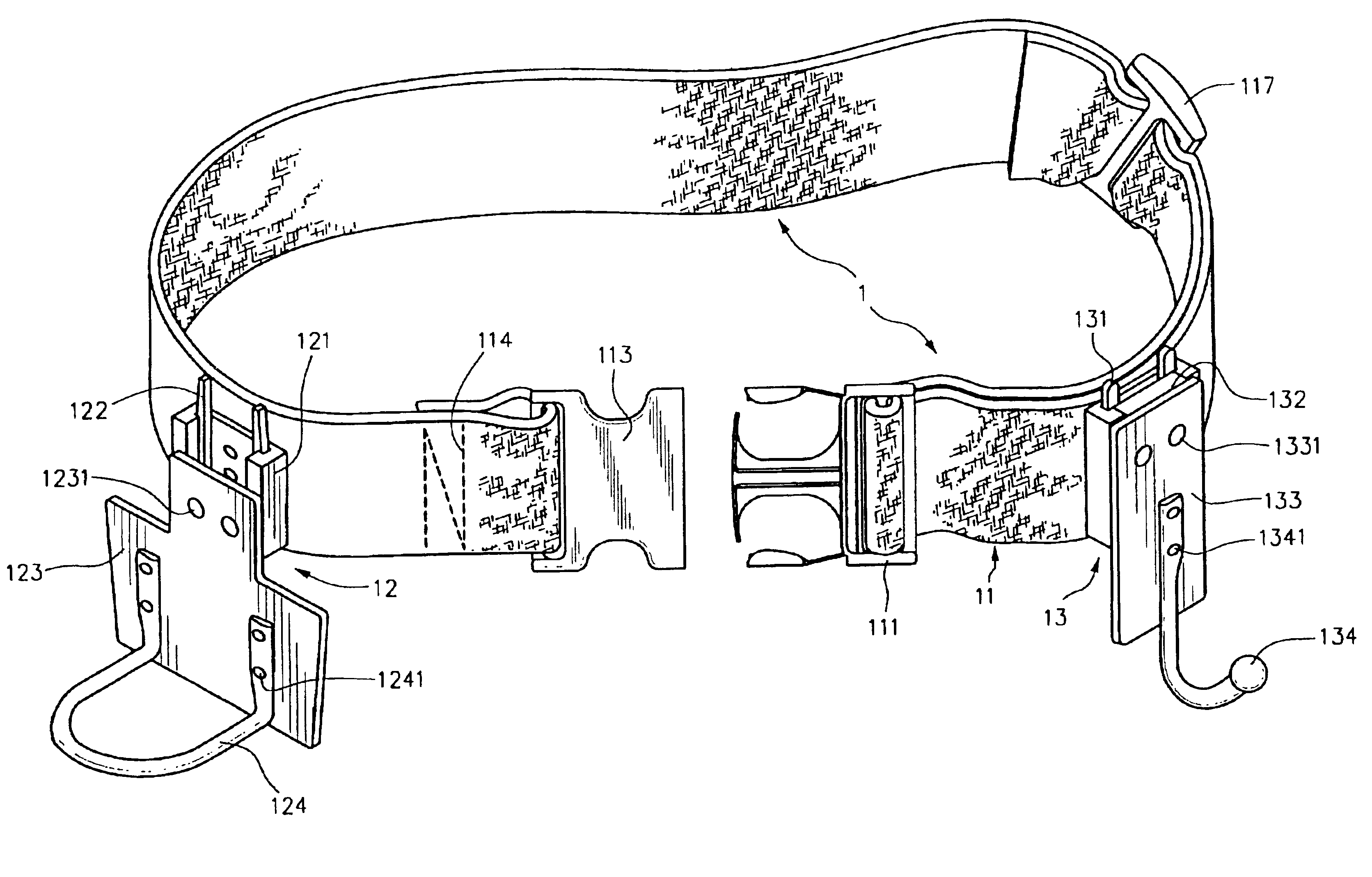
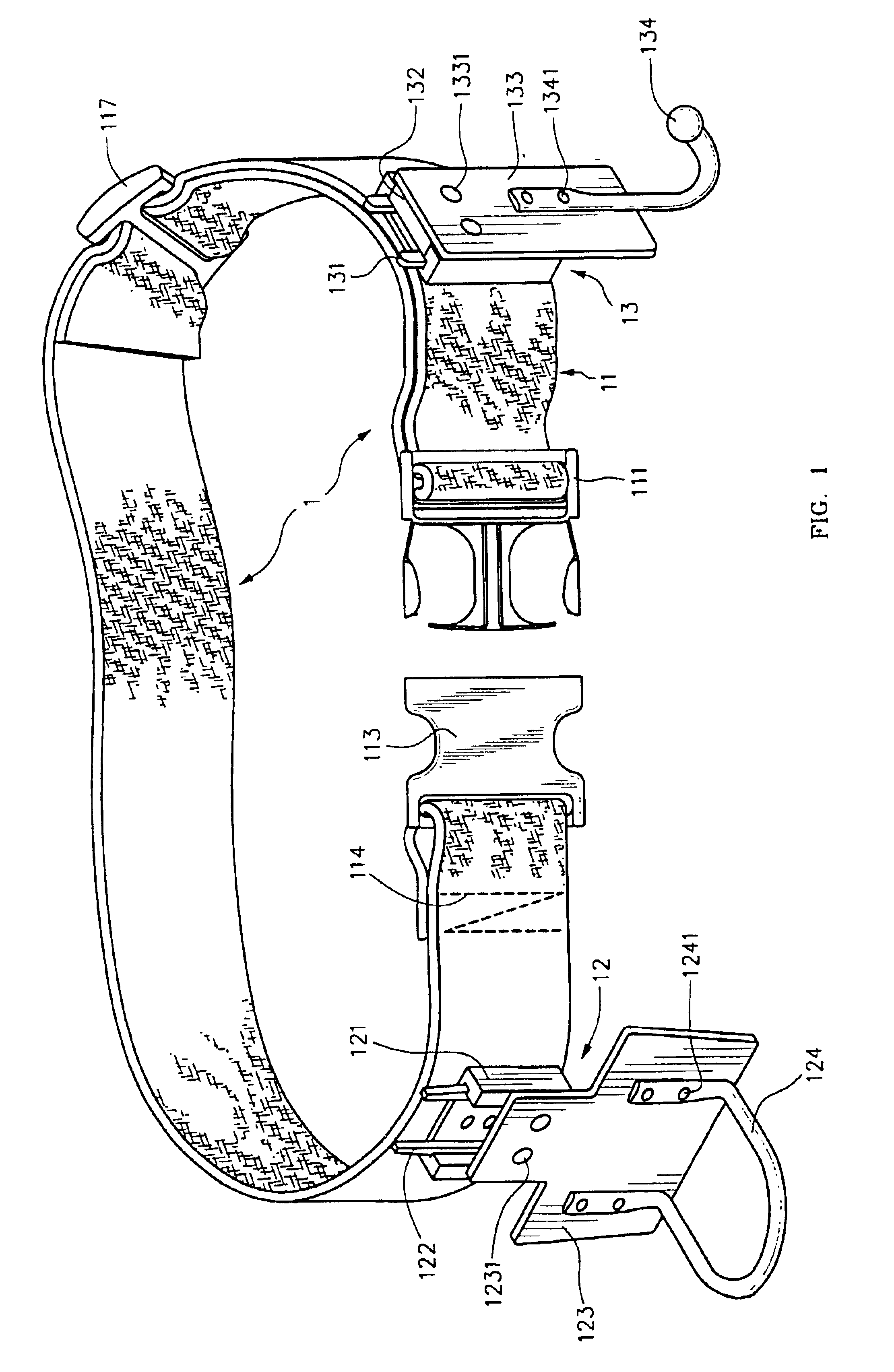
first embodiment
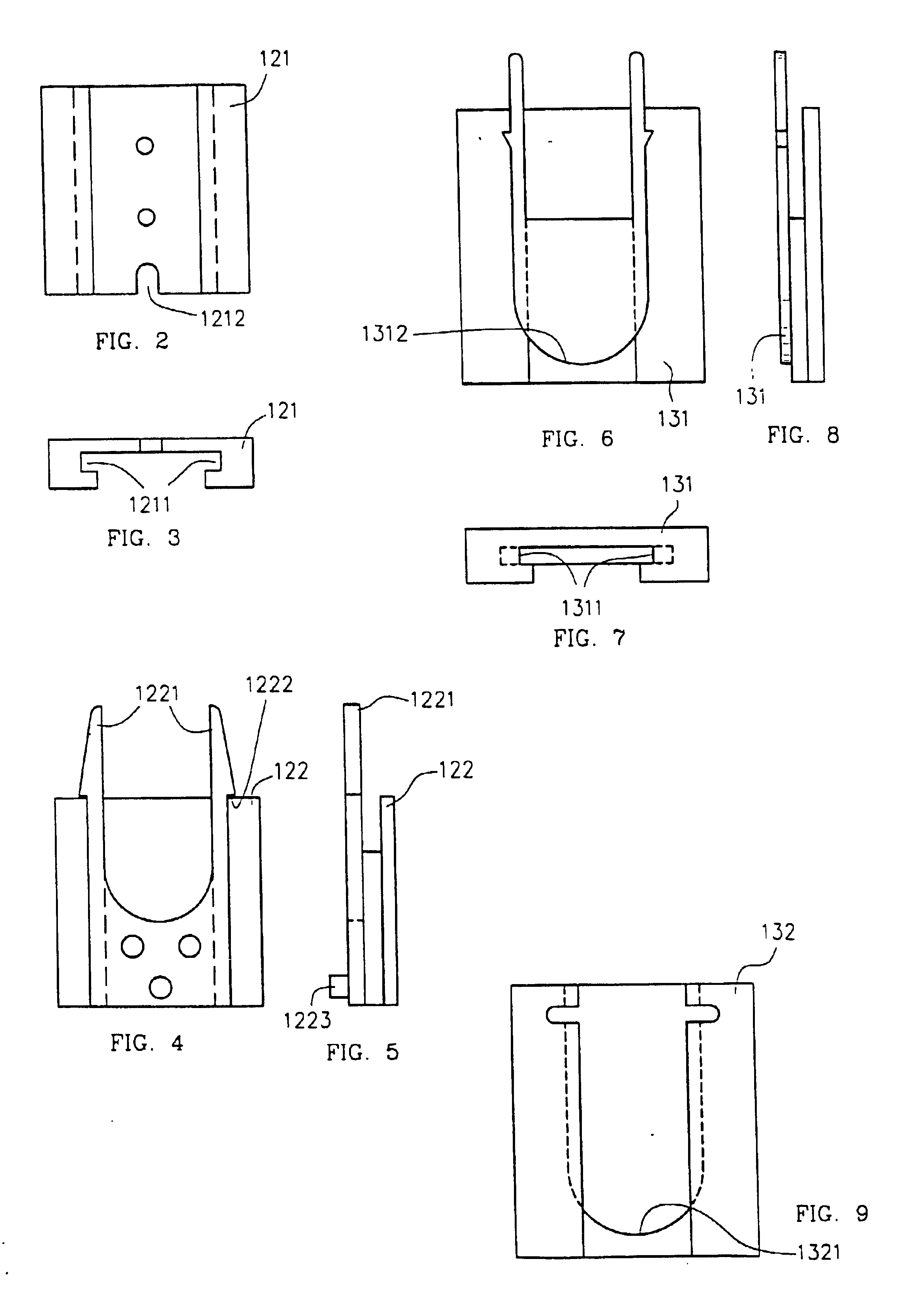
[0088]FIG. 3 is a bottom plan view of a preferred first embodiment of a receiver block that is used in, and part of, the tool belt system in accordance with the present invention previously seen in FIG. 1.
[0089]FIG. 4 is a front plan view, and
[0090]FIG. 5 is a side plan view, of a preferred first embodiment of an attaching block, suitably removably mounted to the first embodiment receiver block shown in FIGS. 2 and 3, that is used in, and part of, the tool belt system in accordance with the present invention previously seen in FIG. 1.
[0091]FIG. 6 is a front plan view,
[0092]FIG. 7 is a top plan view, and
second embodiment
[0093]FIG. 8 is a side plan view of a preferred second embodiment of a receiver block used in, and part of, the tool belt system in accordance with the present invention previously seen in FIG. 1.
[0094]FIG. 9 is a front plan view of a preferred second embodiment of an attaching block, suitably removably mounted to the second embodiment receiver block shown in FIGS. 6 through 8, used in, and part of, the tool belt system in accordance with the present invention previously seen in FIG. 1.
[0095]FIG. 10 is a perspective view of a tool affixing the attaching block previously seen in FIGS. 4 and 5.
[0096]FIG. 11 is a perspective view of a container affixing the attaching block previously seen in FIGS. 4 and 5.
[0097]FIG. 12 is a perspective view of a power tool affixing the attaching block previously seen in FIGS. 4 and 5.
PUM
 Abstract
Description
Claims
Application Information