Hammerlock chuck

a hammerlock and chuck technology, applied in the field of chucks, can solve the problems of increasing the cost and complexity of the chuck, causing the chuck to loosen the grip around the tool shaft, and undesirable consequences

Inactive Publication Date: 2005-02-01
SHANDONG WEIDA MASCH CO LTD
View PDF12 Cites 43 Cited by
  • Summary
  • Abstract
  • Description
  • Claims
  • Application Information

AI Technical Summary

Benefits of technology

At least one pawl is rotatably associated with the gear ring and is configured such that when the gear ring is frictionally locked to the body, the pawl engages the gear ring until application of sufficient torque to overcome the engagement of the pawl with the gear ring. Accordingly, in operation, when the jaws tighten on the shaft of a tool or workpiece, the gear ring is locked to the body and the pawl engages the gear ring so that the jaws are prevented from moving in a non-jaw gripping direction during normal use of the hammerlock chuck.
In another embodiment, the chuck includes a body, a thrust ledge, and jaws slidably positioned in passageways formed in the body. The chuck further includes a ring nut rotatably mounted relative to the body and in engagement with threads on the jaws. A ring driver is disposed in driving engagement with the ring nut so that when the ring driver is rotated with respect to the body, the jaws are moved to grip the shaft of a tool. A gear ring is rotatably located about the body. At least one pawl is provided to engage teeth on the gear ring such that rotation of the ring driver in a jaw gripping direction causes the gear ring to rotate.
In operation, when the ring nut is tightened so that the jaws tightly grip a shaft of a tool or workpiece, the gear ring will frictionally engage the thrust ledge so that the gear ring is rotationally locked to the body. In addition, the pawl engages the gear ring such that rotation of the ring driver and thus movement of the jaws in a non-jaw gripping direction is prevented during normal use of the hammerlock chuck.

Problems solved by technology

In a conventional chuck used for hammer drilling, the vibration that results from use of the tool can cause the jaws to loosen their grip around the shaft of the tool.
This can have undesirable consequences, both for the work piece and for the operation of the tool.
In that patent, however, the chuck requires a front sleeve that has a number of ribs and indentations that may increase the cost and complexity of the chuck.

Method used


Image

  • Hammerlock chuck
  • Hammerlock chuck
  • Hammerlock chuck

Examples


Embodiment Construction

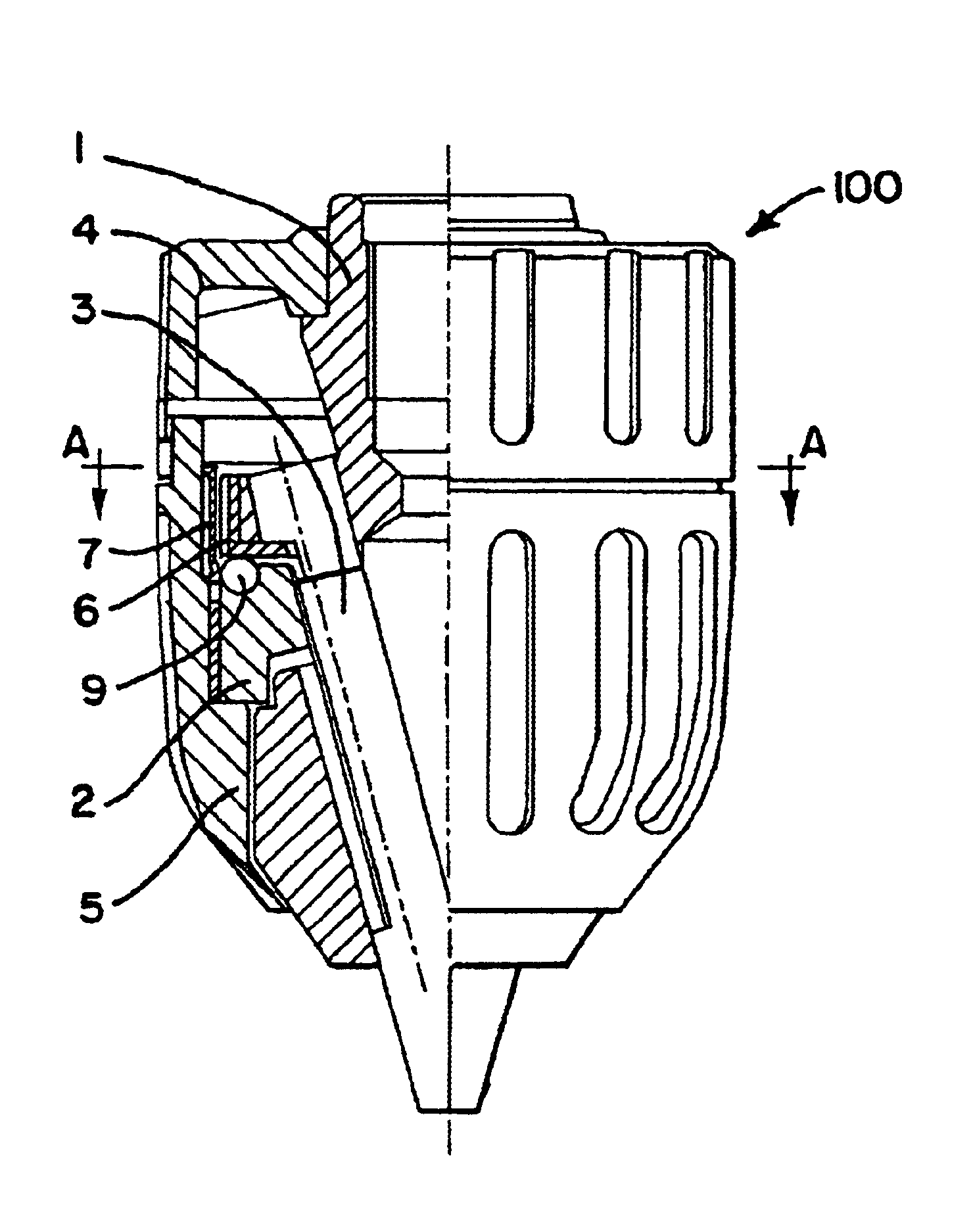
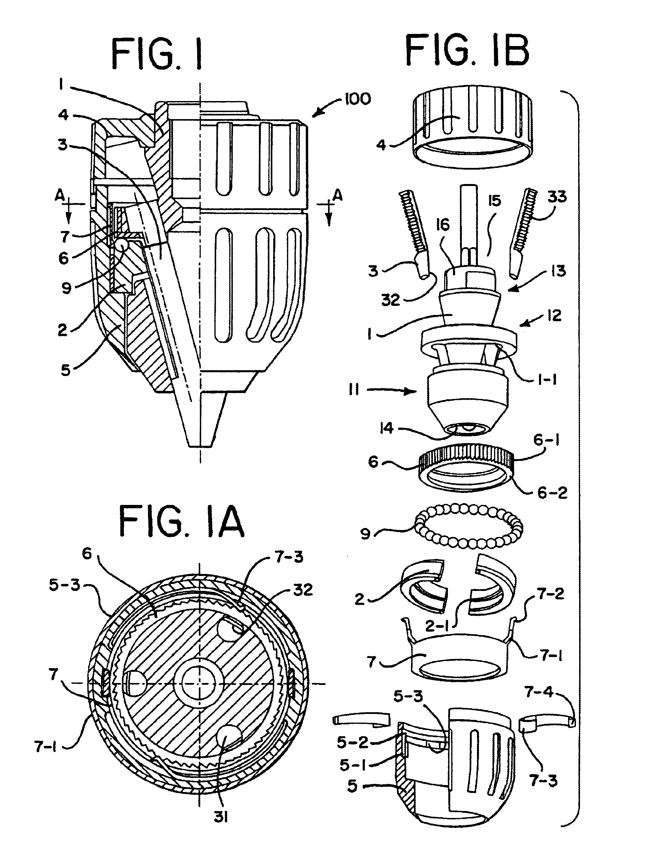
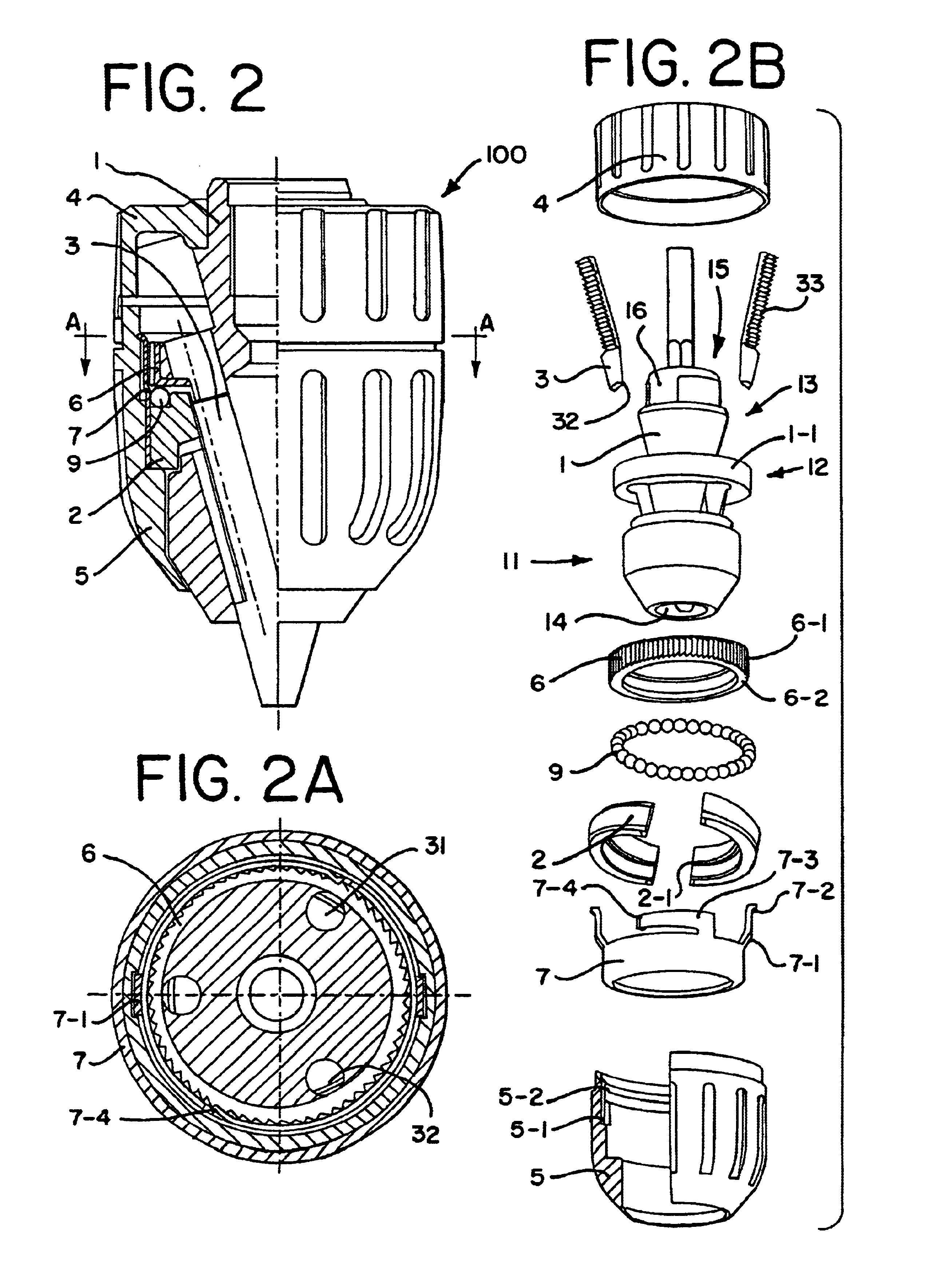
Turning now to FIG. 1, a hammerlock chuck in accordance with the present invention is illustrated. Hammerlock chuck 100 includes a front sleeve 5, an optional rear sleeve 4, a body 1, and a plurality of jaws 3. The body 1 is generally cylindrical in shape and includes a nose or forward section 11, a middle section 12, and a tail or rearward section 13. An axial bore 14 is formed in the nose section 11 of the body 1. The axial bore 14 is somewhat larger than the largest tool shank that the chuck is designed to accommodate.

A threaded bore may be formed in the tail section to mate with the drive shaft of a powered or hand driver (not shown). While a threaded bore may be used, the threaded bore could be replaced with a tapered bore or other suitable shape to mate with a drive shaft. The threaded bore and the axial bore may communicate at the middle section 12 of the body 1. The tail section 13 of the body 1 can include a rear portion 15 with a shaped surface 16 to mate and receive the o...


PUM


Abstract

A chuck for use with a manual or powered driver that may also be used for hammer drilling. The chuck is constructed so that during normal operation for its intended purpose, the jaws holding a shaft for a tool do not loosen. The chuck includes at least one pawl to engage teeth on a gear ring such that rotation of a ring driver in a jaw gripping direction causes the gear ring to rotate. When the jaws tightly grip the shaft, the gear ring will frictionally engage a portion of the chuck so that the gear ring is rotationally locked to the chuck body. At the same time, the pawl engages the gear ring such that rotation of the ring driver and thus movement of the jaws in a non-jaw gripping direction is prevented during normal use of the hammerlock chuck.

Description

BACKGROUNDThe present invention generally relates to chucks for use with drills or with electric or pneumatic power drivers. More particularly, the present invention relates to a keyless chuck that may be tightened or loosened by hand or by actuation of the driver motor. The keyless chuck of the present invention has particular applicability with hammer-type drills or drivers.Both hand and electric or pneumatic tool drivers are well known. Although twist drills are the most common tools used with such drivers, the tools may also comprise screwdrivers, nut drivers, burrs, mounted grinding stones, and other cutting or abrading tools. Since the tools may have shanks of varying diameter or the cross-section of the tool shank may be polygonal, the device is usually provided with a chuck that is adjustable over a relatively wide range. The chuck may be attached to the driver by a threaded or tapered bore.A wide variety of chucks have been developed in the art. In the simplest form of chuc...

Claims


Application Information

Patent Timeline
Patent Type & Authority Patents(United States)
IPC IPC(8): B23B31/12
CPCB23B31/123B23B31/1238Y10T279/17632Y10S279/902B23B2231/38
Inventor YANG, GUIMOTAN, XINGDA
Owner SHANDONG WEIDA MASCH CO LTD
Why Eureka
Try Eureka