Optical light guide member, illumination unit, and instrument

a technology of optical light guide and illumination unit, which is applied in the direction of instrument, planar/plate-like light guide, lighting and heating apparatus, etc. it can solve the problems of increasing the consumption of electric power for illuminating the indicator, affecting the visibility of the indicator, and affecting the effect of the illumination effect, so as to achieve the effect of easy treatment and excellent visibility of the indicator

Inactive Publication Date: 2005-02-01
LEIZ ADVANCED TECH CORP
View PDF15 Cites 12 Cited by
  • Summary
  • Abstract
  • Description
  • Claims
  • Application Information

AI Technical Summary

Benefits of technology

In accordance with the instrument of the present invention, the incident light on the tubular portion from the annular light incident end surface can be effectively emitted from the light exit surface of the flat section, and the visibility for the indicator can be kept excellent with the aid of the transmission illumination.
In the instrument according to the third aspect of the present invention, there may be additionally provided a casing for accommodating the illumination unit such that the illumination unit is protected without fail, and that the treatment thereof is achieved with ease. Particularly, the casing may be the light reflection member of the illumination unit such that the instrument can be made compact.
The optical light guide member or the indicating section may be the light diffusion member of the illumination unit. In this case, it is possible not only to uniformize the intensity and luminance distributions of the light emitted from the light exit surface but also to make the instrument compact.

Problems solved by technology

A light bulb for use in illumination for an instrument equipped in an automobile has a problem in durability against vibration and so on, followed by relatively much consumption of electric power and by difficult exchange of any light bulb when it burned out.
For illumination of the type where light from a light bulb is directly applied to the surface of the indicator illumination efficiency is deteriorated to the utmost at locations far away from the light bulb even if the configuration of a reflector is designed variously, so that it is necessary to arrange a plurality of light bulbs along an outer circumference of the indicator, to result in such inconvenience that the consumption of electric power for illuminating the indicator is increased.
Although in the type of the transmission illumination as described above such inconvenience is moderated, in order to uniformize the light transmitted through the indicator it is necessary to increase a distance from the indicator to the light source, obstructing the instrument to be made compact.

Method used


Image

  • Optical light guide member, illumination unit, and instrument
  • Optical light guide member, illumination unit, and instrument
  • Optical light guide member, illumination unit, and instrument

Examples


Embodiment Construction

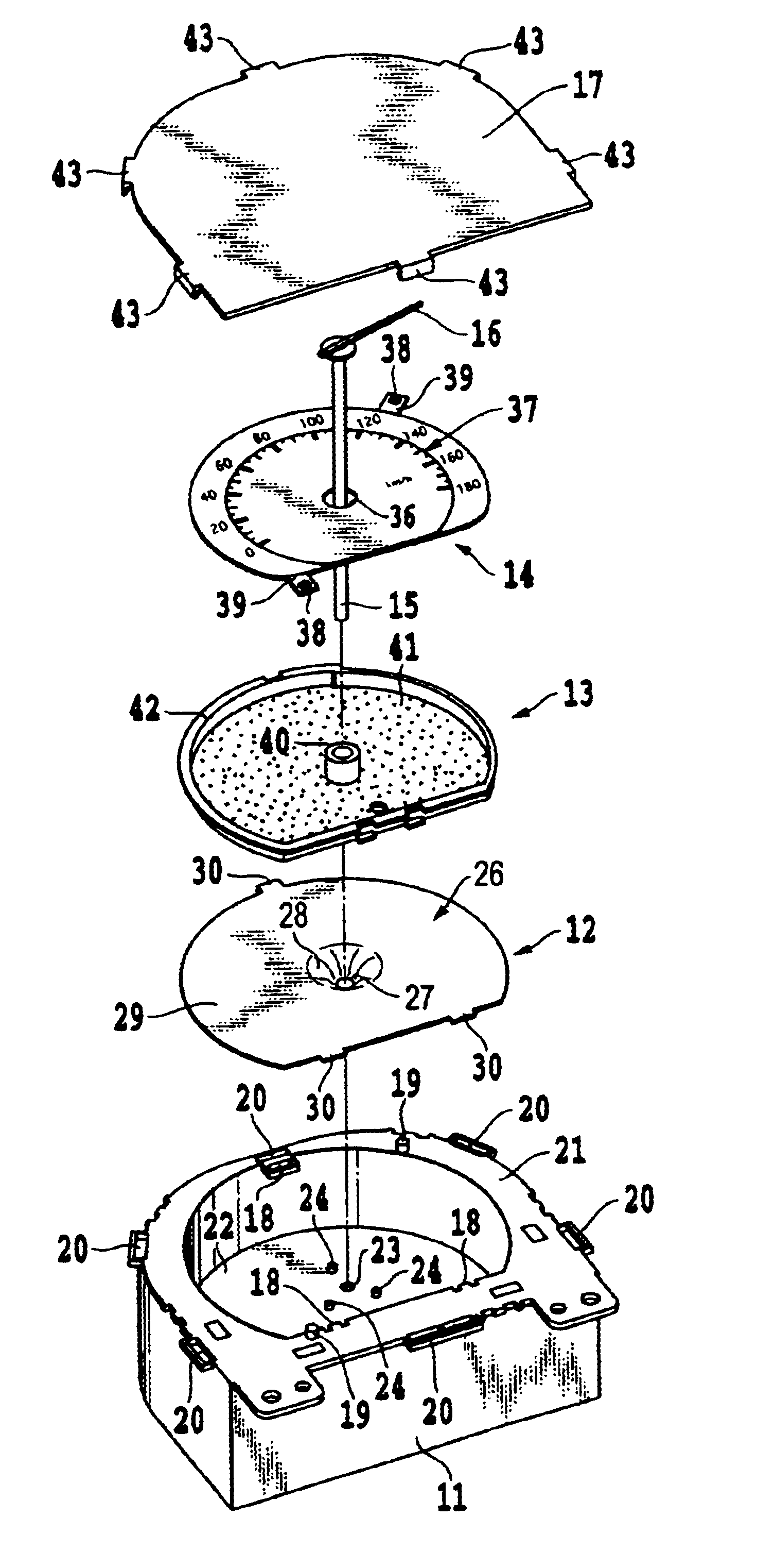
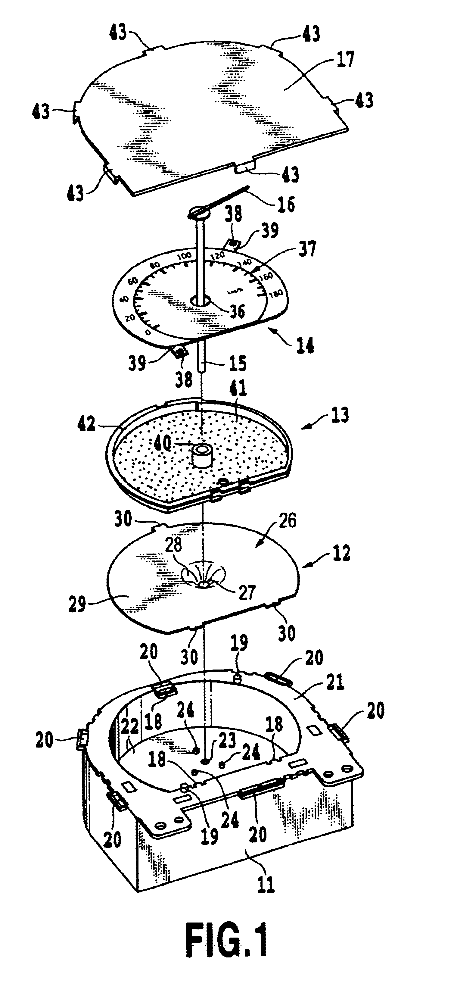
In what follows, there will be described in detail preferred embodiments of the present invention in which an instrument according to the present invention is applied to a speedometer (tachometer) of an automobile and the like with reference to FIGS. 1 to 8. The present invention is however not limited to those preferred embodiments, but it may be further applied to combinations of those embodiments with all alterations and corrections included in the idea of the present invention as claimed in the claims in the present specification. The present invention is therefore applicable to other arbitrary techniques belonging to the spirit of the present invention.

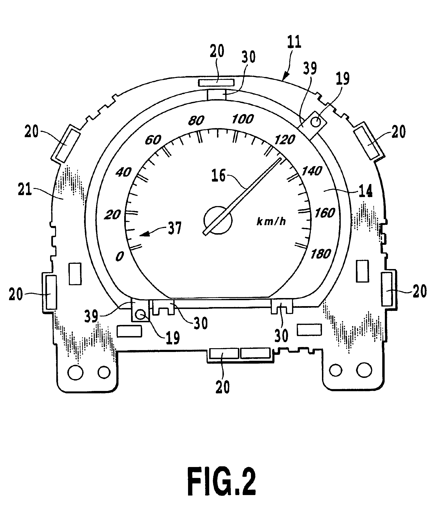
Referring now to FIG. 1, there is illustrated a decomposed state of a main section of a speedometer in the present embodiment, and referring further to FIG. 2 there is illustrated in a frontal view a configuration of the main section in the state thereof where a cover is removed. In the speedometer in the present embodiment, the ...


PUM


Abstract

An optical light guide member according to the present invention includes a tubular portion in which an annular light incident end surface for entering light is formed on a one end thereof, a funnel-shaped expanded section having a one end side thereof continuously extending to the other end of the tubular portion, a flat section which has on a front side thereof a light exit surface extending along a flat plane intersecting an axis of the tubular portion, and which extends continuously to the one end side of the funnel-shaped expanded section, and a plurality of light deflection elements formed at least on the back side of the flat section each for altering the traveling direction of the light. An incident light on the tubular portion from the light incident end surface is emitted with a uniform intensity distribution from the light exit end surface.

Description

This application is based on Japanese Patent Application Nos. 2002-003928 filed Jan. 10, 2002 and 2002-211058 filed Jul. 19, 2002, the contents of which are incorporated hereinto by reference.BACKGROUND OF THE INVENTION1. Field of the InventionThe present invention relates to an optical light guide member for guiding incident light from an annular light incident end surface formed at one end of a tubular portion such that the light is emitted from a light exit surface extending along a flat surface intersecting an axis of the tubular portion, and to an illumination unit and an instrument in which the foregoing optical light guide member is assembled.2. Description of the Related ArtFor illumination for an instrument in a speedometer of an automobile in prior art techniques a light source is provided on an outer circumference of an indicator section to illuminate the indicator section or a light source is provided on the backside of the indicator section having a transparent portion ...

Claims


Application Information

Patent Timeline
Patent Type & Authority Patents(United States)
IPC IPC(8): B60K35/00F21V8/00G01D11/28G02B6/00G12B11/00F21Y101/02
CPCB60K35/00G02B6/002G02B6/0016G01D11/28B60K2350/203B60K2370/33
Inventor KALANTĀR, KALIL
Owner LEIZ ADVANCED TECH CORP
Why Eureka
Try Eureka