
Safety vest and lanyard C-I-P

a safety vest and lanyard technology, applied in the field of safety vests, can solve the problems of serious injury and/or death of workers, and achieve the effects of preventing serious injury to workers, facilitating the use of workers, and reducing weigh

Inactive Publication Date: 2005-02-01
MILLER DONALD M
View PDF22 Cites 8 Cited by
  • Summary
  • Abstract
  • Description
  • Claims
  • Application Information

AI Technical Summary

Benefits of technology

An advantage of the present invention includes the combining of the buoyant life vest with a safety harness. Another advantage is the design may prevent serious injury to the worker if the safety harness is used i.e. in the case of a fall, the novel life vest design may prevent the worker from serious injury or death. Yet another advantage is that both the buoyant life vest and the harness are durable and can withstand significant impact loads in the case where a worker falls. Another advantage is that the safety vest device is easy to don by the worker.
includes the combining of the buoyant life vest with a safety harness. Another advantage is the design may prevent serious injury to the worker if the safety harness is used i.e. in the case of a fall, the novel life vest design may prevent the worker from serious injury or death. Yet another advantage is that both the buoyant life vest and the harness are durable and can withstand significant impact loads in the case where a worker falls. Another advantage is that the safety vest device is easy to don by the worker.
Still yet another advantage is that the device is user friendly so that the worker intuitively knows how to don the buoyant life vest with harness. Another advantage is the full encircling double chest straps across the front buoyant pads. Yet another advantage is that the safety vest device is still buoyant and able to keep the worker afloat in a proper position, even with the inclusion of the harness. In other words, the harness is not so heavy and bulky as to interfere with the buoyancy of the buoyant life vest.
A feature of the present invention is having the D-ring member attached to the center foam panel. In this position, the D-ring member and safety line are positioned in the back of the worker, away from the workers line of sight. Another feature is use of an adjustable buckle member so that a variety of worker sizes can be accommodated.
Yet another feature is that multiple types of buckles can be employed with the life vest herein disclosed including but not limited to side release, nesting and tongue buckles. Still yet another feature is that in-water removal of the safety vest is made easier due to use of the side release buckle, tongue buckle and / or nesting buckle, with the side release buckle, tongue buckle and nesting buckle being intuitively easy for the worker to use.
Still yet another feature is the right leg member has a first end attached to the right foam pad and a second end attached to the center foam pad. The left leg member has a first end attached to the left foam panel and a second end attached to the center foam panel. During use of the harness, the weight of the worker will be distributed to the worker's torso and legs. This type of weight distribution allows for the device to be rated for greater weight since the weight during use is distributed about the entire device. Another feature is the use of grommeted legs with tongue buckles in a second embodiment. Still yet another feature is that the buoyant panels may be joined as a continuous unit so that the vest surrounds the upper torso of the worker.

Problems solved by technology

In such cases, contact between the electrical power line and safety line may result in serious injury and / or death to the worker.

Method used


Image

  • Safety vest and lanyard C-I-P
  • Safety vest and lanyard C-I-P
  • Safety vest and lanyard C-I-P

Examples


Embodiment Construction

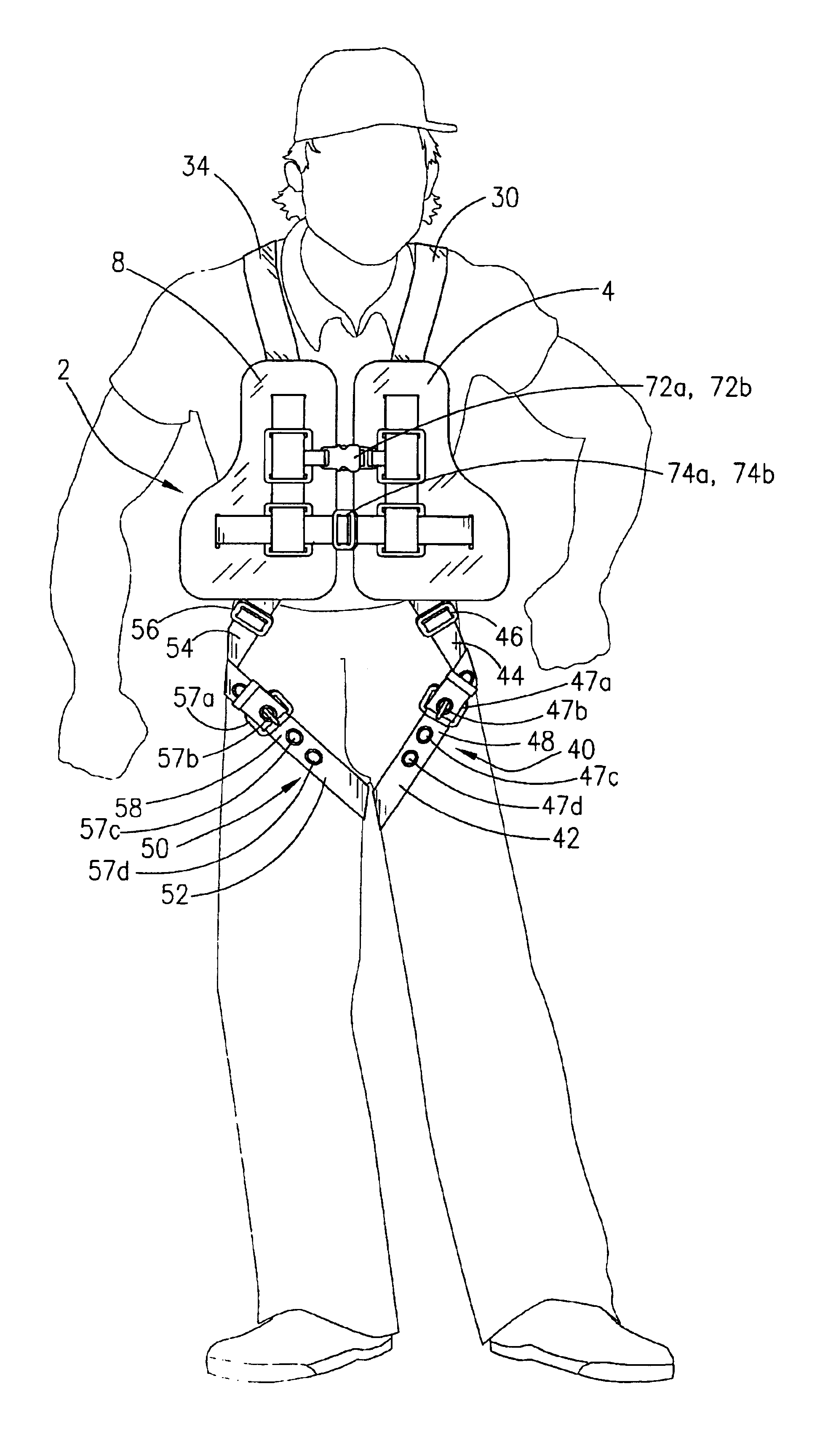
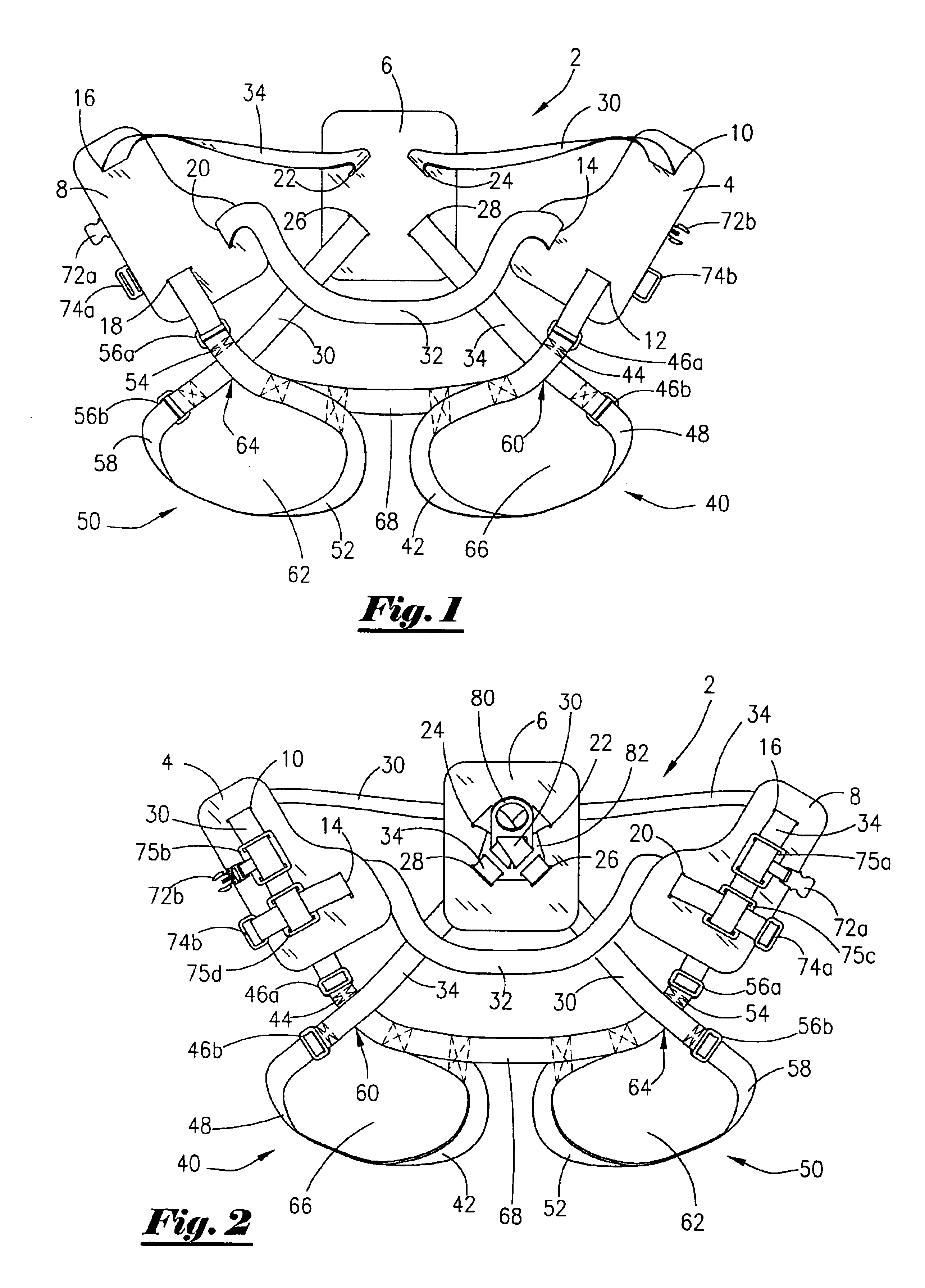
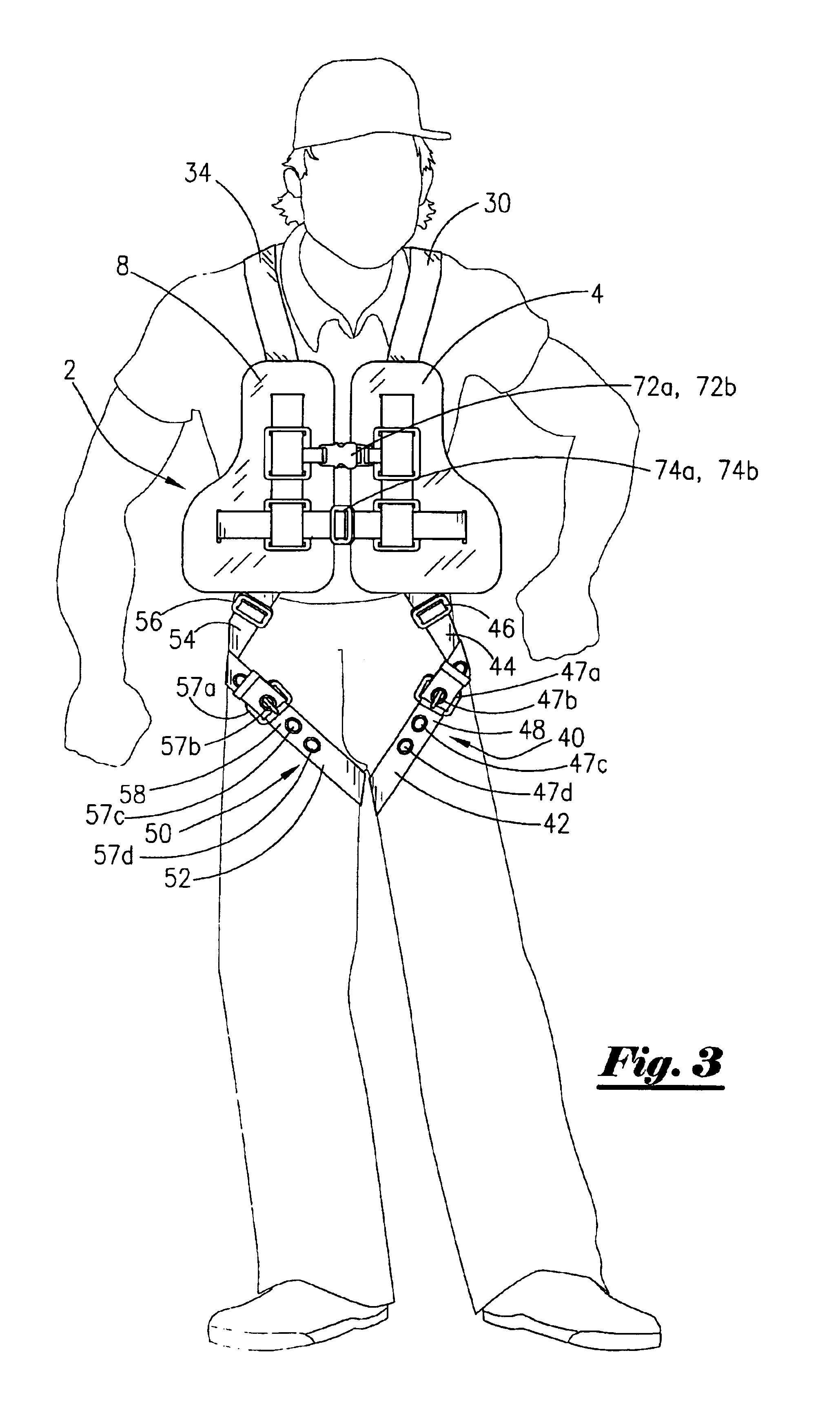
Referring now to FIG. 1, a front view of one embodiment of this invention will now be described. The safety vest device 2 includes a buoyant lift vest and adjustable harness as will be described. The safety vest device 2 has a left buoyant pad 4, a center buoyant pad 6, and a right buoyant pad 8. The buoyancy pads are also referred to as flotation pads and / or panels. The floatation pads are constructed of foam, as is well understood by those of ordinary skill in the art, and in the preferred embodiment, the foam is available from Rubutex, Inc. under the trademark Ensolite. It should also be noted that the pads 4, 6, and 8 may also be referred to as panels.

The flotation pad 4 has a first opening 10 there through, a second opening 12 there through, and a transverse opening 14 there through, with the openings designed to receive the webbing as will be more fully described later in the application. The floatation pad 8 has reciprocal openings, namely, a first opening 16 there through, a...


PUM


Abstract

A safety vest device. The device comprising a right buoyant pad, a center buoyant pad being connected by a first shoulder strap and a left buoyant pad being connected by a second shoulder strap. The device also comprises a right leg strap having an end connected to the right buoyant pad and another end that is connected to the center buoyant pad. Also included is the left leg strap having an end connected to the left buoyant pad and another end that is connected to the center buoyant pad. Also included may be an attaching device that attaches the right buoyant pad to the left buoyant pad. Further, the device may include a ring member attached to the center buoyant pad, and wherein the ring member is configured to attach to a safety lanyard that includes a dielectric component. The device may further comprise a lower strap attached at a first end to the right foam pad and attached at a second end to the left buoyant pad. The lower strap is configured to be inserted through an eyelet in the second end of the left leg strap and through an eyelet in the second end of the right leg strap.

Description

BACKGROUND OF THE INVENTIONThis invention relates to a safety vest. More particularly, but not by way of limitation, this invention relates to a buoyant life vest with a safety harness.In the offshore and marine industries, workers are required to wear a buoyant life vest in the event they are knocked overboard. In the case of dock side workers, the workers may be over land at times and over water at other times. Government regulations generally require that a worker wear a buoyant life vest when his or her work takes the worker over water. Hence, if a worker is knocked from his / her working position over a body of water, the worker will already be wearing a buoyant life vest in order to keep the worker afloat.Another safety device that is employed by workers in the offshore and marine industries is the safety harness. Many times, the worker will be working at heights from several feet above the water line or ground level to several hundred feet from the water line or ground level. T...

Claims


Application Information

Patent Timeline
Patent Type & Authority Patents(United States)
IPC IPC(8): B63C9/00B63C9/115
CPCB63C9/115
Inventor MILLER, DONALD M.
Owner MILLER DONALD M
Learn More